
Anti-shock special drill pipe

A drill pipe and end point technology, applied in drill pipe, drill pipe, earth-moving drilling, etc., can solve the problems of difficulty in cleaning drill pipe, poor gas discharge and anti-shock pressure effect, waste of materials, etc., to reduce the labor intensity of workers , Improve drilling efficiency, fast and flexible connection effect

Active Publication Date: 2020-12-04
山东兖能泰德重工有限公司
View PDF11 Cites 0 Cited by
  • Summary
  • Abstract
  • Description
  • Claims
  • Application Information

AI Technical Summary

Problems solved by technology

[0003] When drilling with conventional water circulation, it is easy to collapse the hole, cause serious drill sticking, and the drilling depth cannot reach the design target, resulting in poor gas discharge and anti-rock impact effects, which cannot well meet the requirements of production and development, and affect the normal production of coal mines. conduct
[0004] The drill pipe in the prior art has two defects in the construction. The one is that the valve at the end of the drill pipe is not opened, and it is difficult for construction workers to find out at this time. The rods cause great difficulties and affect the construction; the second is that because the design requires a pile head of a certain height on the upper part of the pile, the existing drill pipe is controlled by the experience of the construction personnel, resulting in an excessive error in the height of the pile head. It needs to be removed manually, which is a waste of manpower and waste of materials. If it is too low, it does not meet the design requirements
[0005] At the same time, when the drill pipe in the prior art is removing chips while working, due to the defect of the rotary wing structure, the strength of each section of chip removal is basically the same, resulting in the blockage of chip removal.

Method used


Image

  • Anti-shock special drill pipe
  • Anti-shock special drill pipe
  • Anti-shock special drill pipe

Examples


Embodiment Construction

[0042] The above and other technical features and advantages of the present invention will be described in more detail below in conjunction with the accompanying drawings.

[0043] Preferred embodiments of the present invention are described below with reference to the accompanying drawings. Those skilled in the art should understand that these embodiments are only used to explain the technical principle of the present invention, and are not intended to limit the protection scope of the present invention.

[0044] It should be noted that, in the description of the present invention, terms such as "upper", "lower", "left", "right", "inner", "outer" and other indicated directions or positional relationships are based on the terms shown in the accompanying drawings. The direction or positional relationship shown is only for convenience of description, and does not indicate or imply that the device or element must have a specific orientation, be constructed and operated in a speci...


PUM


Abstract

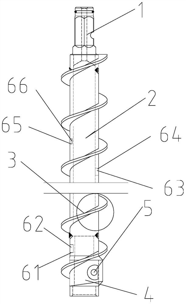
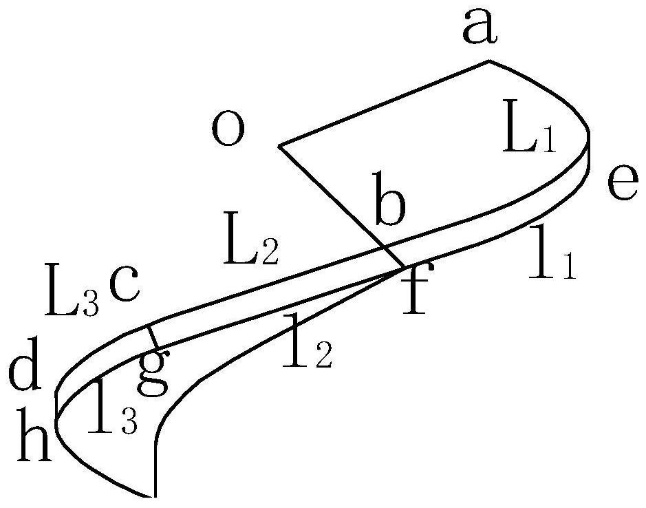
The invention relates to an anti-impact special drill pipe. A hexagonal pyramid handle is arranged on the tail portion of the drill pipe, a hexagonal pyramid hole is formed in the front portion of thedrill pipe, flat pin holes are formed in the front portion of the drill pipe and the hexagonal pyramid handle, and fins are arranged on the periphery of the drill pipe. The fins are arranged symmetrically, the shape of first outer arc segments of the fins is determined according to the following formula (1), L1 represents the arc length of the first outer arc segments, R represents the radius ofthe drill pipe, and alpha represents the central angle from a first endpoint a to a second endpoint b. The anti-scour special drill pipe solves the problem of drilling and hole forming in a soft and protruding coal seam in an underground coal mine, realizes chip removal while drilling, reduces the labor intensity of workers, and improves the drilling efficiency. The connection is fast and flexible, and the adaptive performance is high. The anti-impact special drill pipe takes the strength of the first outer arc segments combined with the fins as reference parameters, and maintains a fixed stress intensity value when the drill pipe is in work, so that no retardation is achieved, and the drilling efficiency is further improved.

Description

technical field [0001] The invention relates to the technical field of drilling tool accessories for engineering drilling and coal seam prospecting, in particular to a special anti-shock drill pipe. Background technique [0002] In many mines in my country, the coal seams have poor air permeability, soft coal quality, high gas content, and even dynamic phenomena or outburst dangers, making it extremely difficult to drill coal seam pre-drainage boreholes. [0003] When drilling with conventional water circulation, it is easy to collapse the hole, cause serious drill sticking, and the drilling depth cannot reach the design target, resulting in poor gas discharge and anti-rock impact effects, which cannot well meet the requirements of production and development, and affect the normal production of coal mines. conduct. [0004] The drill pipe in the prior art has two defects in the construction. The one is that the valve at the end of the drill pipe is not opened, and it is dif...

Claims


Application Information

Patent Timeline
Patent Type & Authority Patents(China)
IPC IPC(8): E21B17/22E21B44/02E21B49/00
CPCE21B17/22E21B44/02E21B49/003
Inventor 刘亚高旭苗青王保勤张松林李亮
Owner 山东兖能泰德重工有限公司
Learn More