Hydraulic system on-site data acquisition terminal based on pipeline for mining

A technology of hydraulic system and field data, applied in the field of hydraulic equipment, to achieve the effect of high integration and operation automation, improved flexibility, and strong data communication capabilities

Pending Publication Date: 2018-12-07
JIAOZUO HUAFEI ELECTRONIC & ELECTRIC CO LTD
View PDF0 Cites 0 Cited by
  • Summary
  • Abstract
  • Description
  • Claims
  • Application Information

AI Technical Summary

Problems solved by technology

[0003] Aiming at the deficiencies in the prior art, the present invention provides a pipeline-based on-site data acquisition terminal for mining hydraulic systems. The invention has simple structure, good versatility, high degree of integration and operation automation. On the one hand, it can effectively communicate with various The joint use of the same pipe diameter and the hydraulic pipeline of the use site greatly improves the flexibility, versatility and site adaptability of the use, and the parts can be flexibly adjusted and replaced according to the use needs, thus further effectively improving the hydraulic pressure. The present invention has the flexibility of use and the efficiency of fault repair operations. On the other hand, the data detection is comprehensive, the detection accuracy is high, and the data communication capability is strong. Remote transmission of detection data improves the flexibility and efficiency of detection work, and reduces the labor intensity of detection operations, thereby greatly improving the reliability, flexibility, and convenience of hydraulic oil working state detection operations in hydraulic systems, and effectively Make up for the defects of untimely detection, missed detection and high labor intensity and high cost of detection work that are easy to occur in traditional low detection operations

Method used


Image

  • Hydraulic system on-site data acquisition terminal based on pipeline for mining

Examples


Embodiment Construction

[0015] In order to make the technical means, creative features, goals and effects achieved by the present invention easy to understand, the present invention will be further described below in conjunction with specific embodiments.

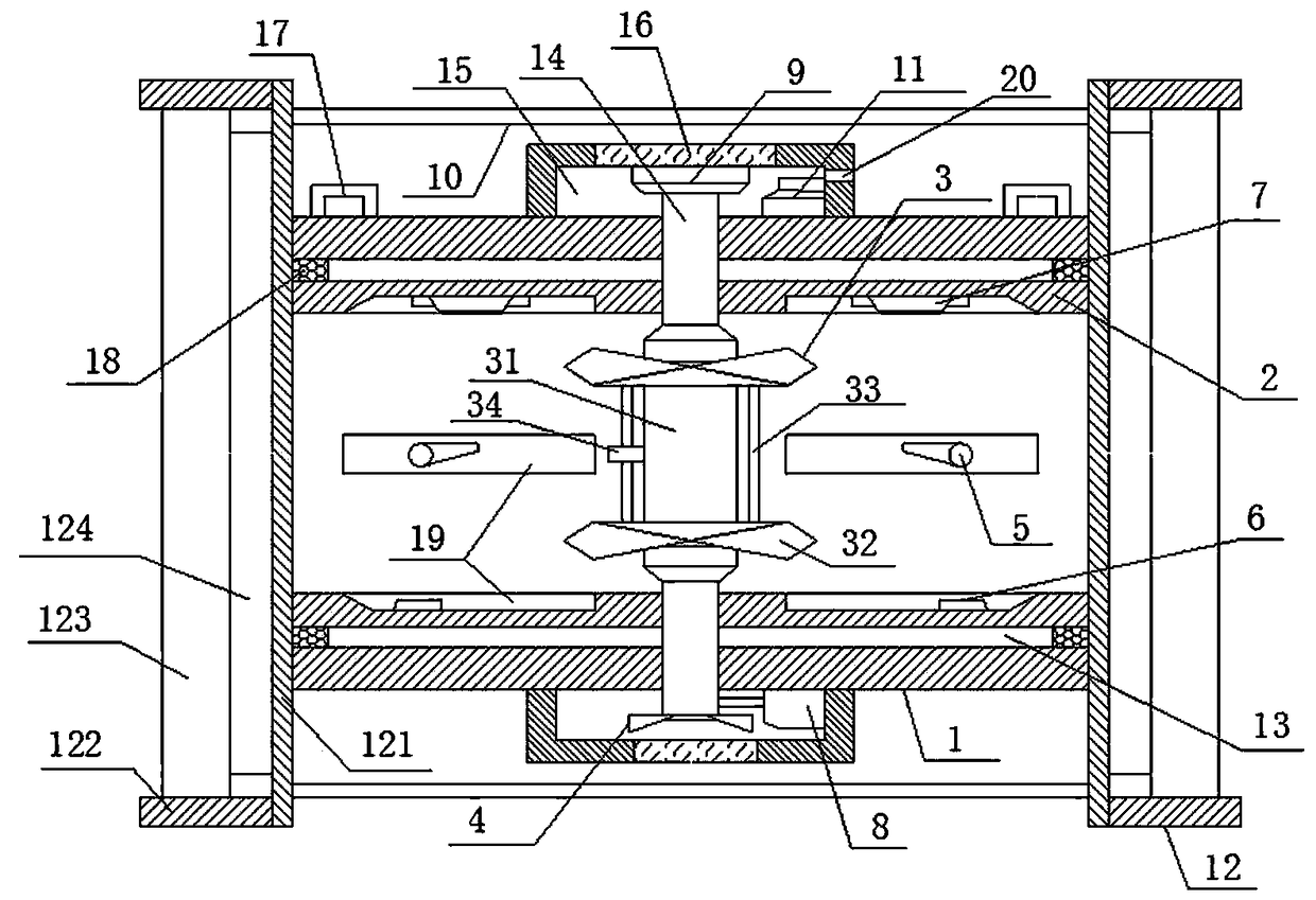
[0016] Such as figure 1 The on-site data acquisition terminal of a pipeline-based mine hydraulic system includes a bearing shell 1, a bearing inner tank 2, a pulsator 3, an indicating impeller 4, an online oil sensor 5, an oil pressure sensor 6, a flow sensor 7, a rotational speed The sensor 8, the brake mechanism 9, the positioning screw 10 and the detection control circuit 11, the bearing shell 1 is a hollow tubular structure with a rectangular axial section, and its front and rear ends are provided with connecting flanges 12, and are located on both sides of the bearing shell 1. The rear end faces of the connecting flange 12 at the end position are connected to each other by at least three positioning screws 10, the axes of the positioning scre...


PUM


Abstract

The invention relates to a hydraulic system on-site data acquisition terminal based on a pipeline for mining. The terminal comprises a bearing shell, a bearing inner container, a wave wheel, an indicating impeller, an on-line oil quality sensor, an oil pressure sensor, flow sensors, a rotating speed sensor, a braking mechanism, a positioning screw rod and a detection control circuit. The front endface and the rear end of the bearing shell are provided with connecting flanges, the bearing inner container is embedded in the bearing shell, the wave wheel is embedded in the bearing inner container, two ends of the wave wheel are connected with the indicating impeller and the braking mechanism respectively through transmission shafts; the online oil quality sensor, the oil pressure sensor andthe flow sensors are distributed on the inner surface of the bearing inner container. The terminal, on one hand, can be effectively used in cooperation with hydraulic pipelines with various pipe diameters or in various use sites, flexibility and universality of use and site adaptability are greatly improved, on the other hand, the data detection is comprehensive, detection precision is high, datacommunication capability is high, and the requirements of comprehensive and continuous detection operation of important working parameters such as grease, oil pressure and the like of hydraulic oil can be effectively realized.

Description

technical field [0001] The invention relates to a hydraulic system detection device, which belongs to the technical field of hydraulic equipment. Background technique [0002] At present, in the industrial production activities of mining operations and equipment such as vehicles and aircrafts, it is often necessary to use the driving mechanism of the operation equipment of the hydraulic system, in order to improve the reliability and stability of the operation of the hydraulic system, and timely discover the hidden dangers of accidents in the hydraulic system, etc. At present, it is mainly to add auxiliary detection devices such as oil quality detection equipment and oil pressure detection equipment to the hydraulic system, so as to detect important parameters such as oil pressure and oil quality of the hydraulic oil that plays the main role in the work of the hydraulic system to ensure Timely detection of hidden dangers of hydraulic system accidents and timely grasp of th...

Claims


Application Information

Patent Timeline
Patent Type & Authority Applications(China)
IPC IPC(8): F15B19/00
CPCF15B19/00
Inventor 赵辉刘东耀夏宏强王亚洲李明振高瑞凯杨海鹏
Owner JIAOZUO HUAFEI ELECTRONIC & ELECTRIC CO LTD
Why Eureka
Try Eureka