Automobile bearing self-control oil injection device

An oil injection device and a technology for automobile bearings, which are applied in the direction of lubricating oil input, lubricating parts, mechanical equipment, etc., can solve problems such as failure to meet precision requirements, waste, and affect bearing life, and achieve fast and convenient placement of bearings and low production costs , high work efficiency

Pending Publication Date: 2018-12-07
QINGDAO UNIV OF SCI & TECH
View PDF0 Cites 6 Cited by
  • Summary
  • Abstract
  • Description
  • Claims
  • Application Information

AI Technical Summary

Problems solved by technology

However, the existing bearing oiling process has a low degree of automatic control, which is generally done manually or mechanically.
Manual oiling is prone to oil leakage, uneven oiling, time-consuming and labor-intensive, which reduces the efficiency of oiling; in addition, the gap in the hub bearing is invisible, and the operator has a low degree of control over the amount of oil injected, and it is difficult to ensure that the gap is completely filled with butter. It cannot meet the precision requirements; if the lubrication is not enough, it will cause excessive wear of the bearing; if the amount of grease injected is too much, it will not only cause unnecessary waste, but more seriously, it will cause the temperature of the bearing to rise and affect the life of the bearing
It can be seen that the traditional manual oiling method is difficult to meet the needs of the society. However, large-scale mechanical oiling equipment is expensive and complicated to operate, which cannot meet the application needs of ordinary enterprises; therefore, it is urgent to develop a new type of oiling device to solve these problems.

Method used


Image

  • Automobile bearing self-control oil injection device
  • Automobile bearing self-control oil injection device
  • Automobile bearing self-control oil injection device

Examples


Embodiment Construction

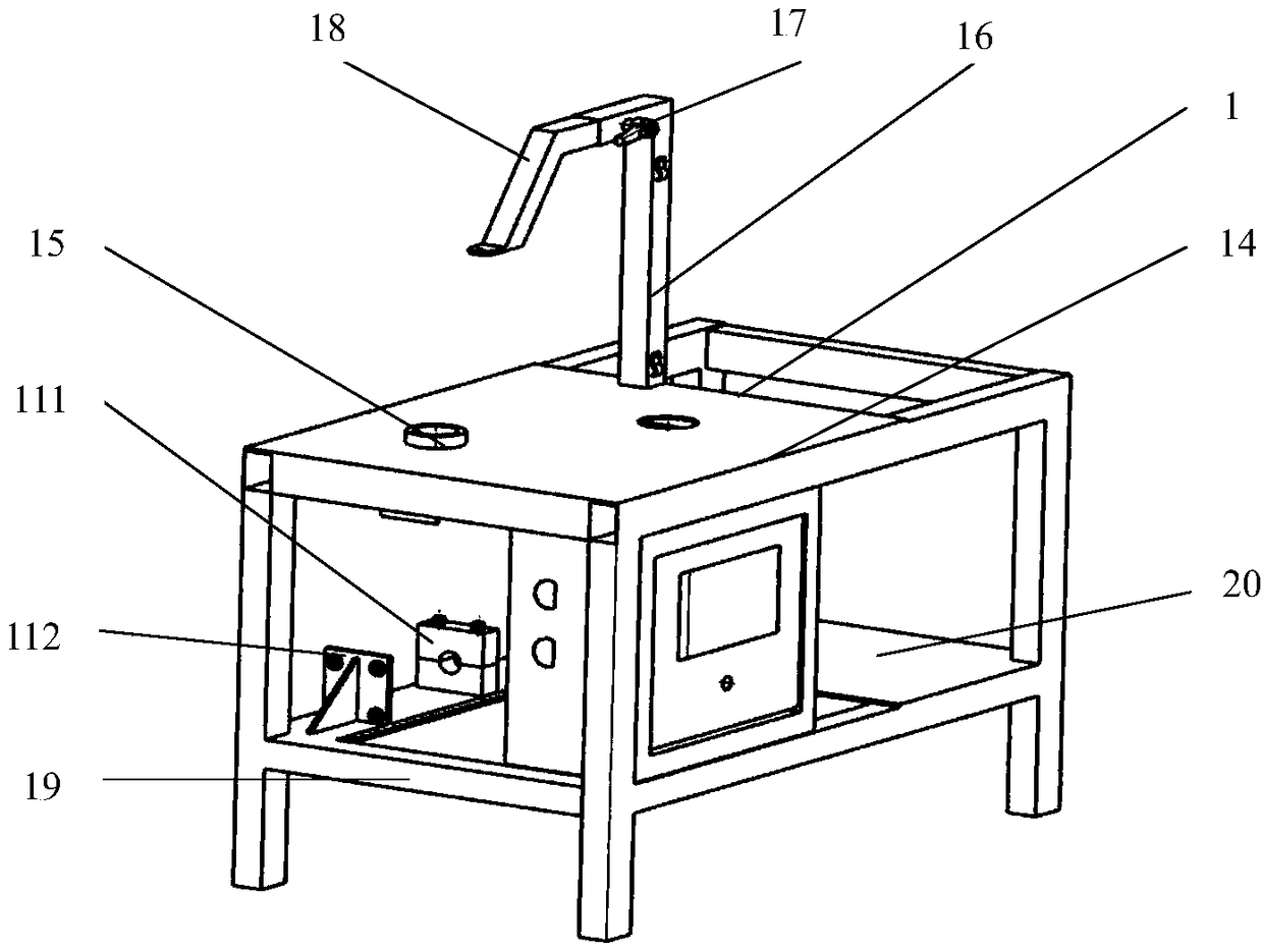
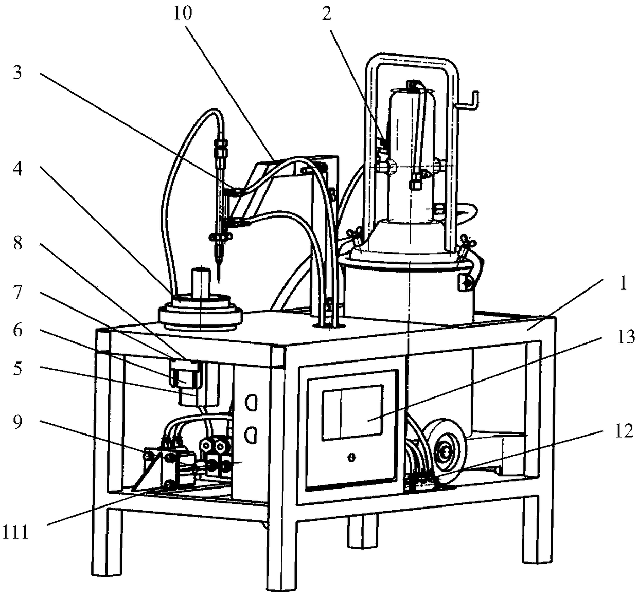
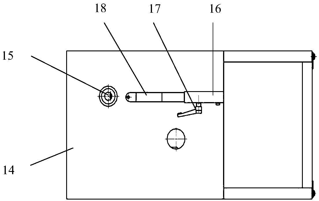
[0025] The implementation process of the oil injector of the present invention is described in detail in conjunction with the accompanying drawings. Such as Figure 1-Figure 6 As shown, a self-control oiling device for automobile bearings includes a frame 1, and the frame 1 is composed of a workbench 14, an oil injection support rod 16, an oil injection arm 18, a support handle 19, a pipeline support plate 111, and a cylinder backing plate 112. The oil injection arm Tightening handle 17 is housed on it, and the length of arm can be adjusted so as to adjust the horizontal distance between grease nipple 29 and bearing 44. One side of the frame 1 is provided with an oil drum placement hole, and the oil drum 21 is supported by the support plate 20; the other side is provided with a bearing 44 fixing hole, and the bearing 44 is fixed by the rotating shaft 45 and the conical pressure plate 43, and the installation steps under the workbench The motor 5 is connected to the bearing 44...


PUM


Abstract

The invention relates to an automobile bearing self-control oil injection device. The automobile bearing self-control oil injection device comprises a rack. The rack is composed of a workbench, an oilinjection supporting rod, an oil injection arm, a supporting rod, a pipeline supporting plate and an air cylinder backup plate. An oil bucket installing hole is formed in one side of the rack, and anoil bucket is supported through a supporting plate; and a bearing fixing hole is formed in the other side, a bearing is fixed through a rotation shaft and a conical pressing disc, and a stepping motor is arranged below the workbench and connected with the bearing through a coupler. An oil injector is provided with a pneumatic oil pressing mechanism and a stroke control mechanism, the stepping oilpressing function is achieved through an electromagnetic valve and an air cylinder, and the oil pressing mechanism is connected through an oil path pipeline. A core component of the shown device is arranged in a control box, and self-control running of the oil injection device is achieved through PLC system programming. According to the designed bearing self-control oil injection device, the oilinjection work efficiency is obviously improved, the product size is small, operation is simple, the production cost is low, and practicability is high.

Description

technical field [0001] The invention relates to an automatic control device for injecting grease into a hub bearing of an automobile, and belongs to the technical field of bearing oiling equipment. Background technique [0002] Auto parts maintenance is a labor-intensive industry. With the rapid growth of domestic labor costs, improving the level of equipment automation, reducing staff and increasing efficiency has become an important trend of development. In order to achieve its high-precision, high-efficiency and high-intelligence functions, auto parts maintenance equipment gradually applies mechatronics technology, integrating various cutting-edge disciplines and technologies such as precision mechanical structure, servo drive, and automatic control technology. For the rolling bearings of automobile hubs, in order to make them have good rotational performance and a long service life, grease is generally injected between the inner ring and the outer ring to ensure lubricat...

Claims


Application Information

Patent Timeline
Patent Type & Authority Applications(China)
IPC IPC(8): F16N37/00
CPCF16N37/003
Inventor 梁晓明高心心于立华
Owner QINGDAO UNIV OF SCI & TECH
Why Eureka
Try Eureka