
Optical conductor and lighting system for vehicle

A lighting system and light conductor technology, applied in the field of light conductors, can solve the problems of high cost, unfavorable construction space requirements and weight, and increased cost, and achieve the effects of reducing cost, reducing the possibility of failure, and reducing system complexity.

Active Publication Date: 2018-12-07
VOLKSWAGEN AG
View PDF11 Cites 0 Cited by
  • Summary
  • Abstract
  • Description
  • Claims
  • Application Information

AI Technical Summary

Problems solved by technology

[0005] It is clear that the illuminating devices known hitherto have the disadvantage that they always use a plurality of parts with a partly very complex structure for a clearly separated light function
This results in higher costs
Especially in the field of vehicles where a high number of components occurs, this leads to increased costs (Skalierung)
The high installation space requirement and the weight of the required components for the known solutions are disadvantageous also in the field of vehicles

Method used


Image

  • Optical conductor and lighting system for vehicle
  • Optical conductor and lighting system for vehicle
  • Optical conductor and lighting system for vehicle

Examples


Embodiment Construction

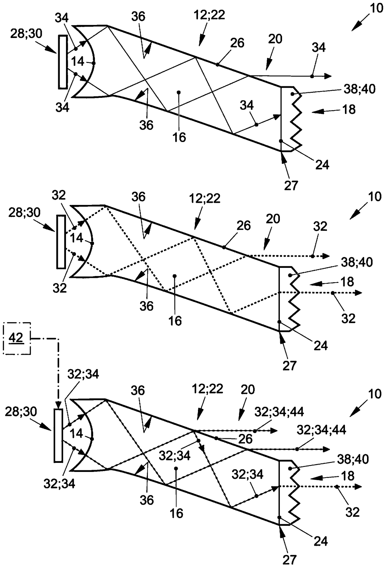
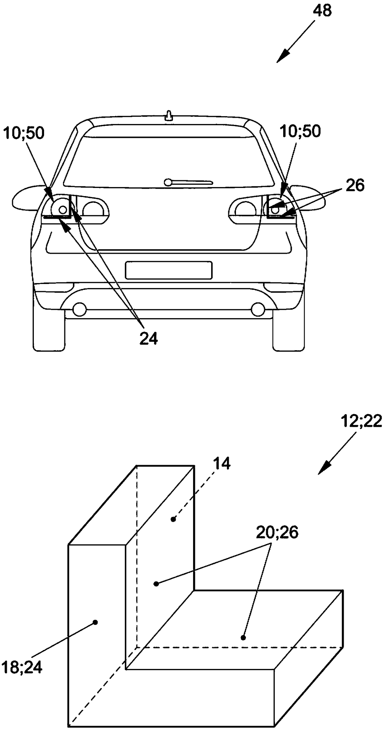
[0041] figure 1 A lighting system 10 according to the invention is shown which has a light guide 12 according to the invention. The light guide 12 comprises a light entry region 14 , a light guide region 16 as well as a first light exit region 18 and a second light exit region 20 . The light guide 12 is here a surface light guide 22 . The flat light conductor 22 has an end face 24 and a side face 26 . The first light exit region 18 is arranged on the end face 24 and the second light exit region 20 is arranged on the side face 26 .

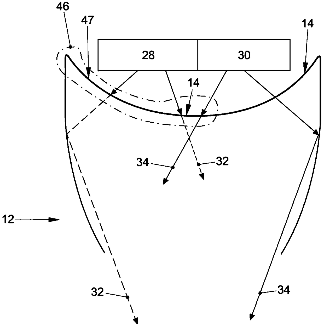
[0042] The lighting system 10 also has a first light source 28 and a second light source 30 . The first and second light sources 28 , 30 are arranged upstream of the light entry region 14 such that the light emitted by them impinges on the light guide 12 . The first and second light sources 28 , 30 are shown one behind the other in this view, that is to say shifted into the plane of the drawing. They are therefore not shown individually here. ...


PUM


Abstract

The invention relates to an optical conductor (12), and different light functions are unified in a compact and low-complexity technical solution through the optical conductor. This is achieved in thefollowing manner, ie, light of different wavelengths (32,34) can be incident into the optical conductor (12), and the light of the first wavelength (32) and the light of the second wavelength (34) canbe selectively emitted at different light emergent areas (18, 20). This is realized in the following manner, ie, a light emergent area (18) is designed to be non-transparent to light of one wavelength, and the other light emergent region (20) is designed to be transparent. The invention further relates to a lighting system with the optical conductor and a motor vehicle having the lighting systemor the optical conductor.

Description

technical field [0001] The invention relates to a light guide comprising a light entry area, a light guide area, a first light exit area and a second light exit area, the invention also relates to a lighting system for a vehicle having a light guide, said The light guide comprises a light incident region, a light guide region, and first and second light exit regions; having first and second light sources, wherein the first light source is capable of generating light of a first wavelength, and the second light source is capable of generating light of a second wavelength Light, the invention also relates to a motor vehicle comprising a light guide or a lighting system. Background technique [0002] DE 10 2008 057 538 A1 discloses a vehicle light with a chamber and a reflector with a plurality of light sources. The light sources can generate light in different wavelength ranges which have different priorities, wherein the priority is technically determined by the fact that the...

Claims


Application Information

Patent Timeline
Patent Type & Authority Applications(China)
IPC IPC(8): F21S43/243F21S43/245F21S43/20F21S43/14F21V23/00F21W103/10F21W103/20F21W107/10F21Y113/10F21Y115/10
CPCF21S43/14F21S43/243F21S43/245F21S43/255F21V23/003F21Y2113/10F21Y2115/10F21W2107/10F21W2103/10F21W2103/20B60Q1/2607B60Q2400/20F21S43/241F21W2103/35
Inventor B.里克特M.汉泽尔
Owner VOLKSWAGEN AG
Learn More