
Sub-channel flow sampling device and method

A sampling device and channel flow technology, applied in the field of sampling, can solve problems such as difficulty in ensuring the accuracy of measurement results and difficulty in realization, and achieve the effects of easy processing, low cost, and convenient operation

Active Publication Date: 2018-12-07
XI AN JIAOTONG UNIV
View PDF12 Cites 2 Cited by
  • Summary
  • Abstract
  • Description
  • Claims
  • Application Information

AI Technical Summary

Problems solved by technology

The existing sub-channel flow sampling technology still has some shortcomings and deficiencies, such as Pitot tube, hot wire velocimeter and other intrusive flow velocity measurement methods to measure flow velocity, which will affect the flow field at the outlet of the component, and it is difficult to guarantee the accuracy of the measurement results; The non-contact measurement method PIV can only measure the rod bundle component channel with a large distance between the rod bundles, which does not affect the laser propagation and has no wire wrapping. There are very high requirements on the refractive index of the rod bundle material of the test pipe and the test working fluid, and it is difficult to realize

Method used

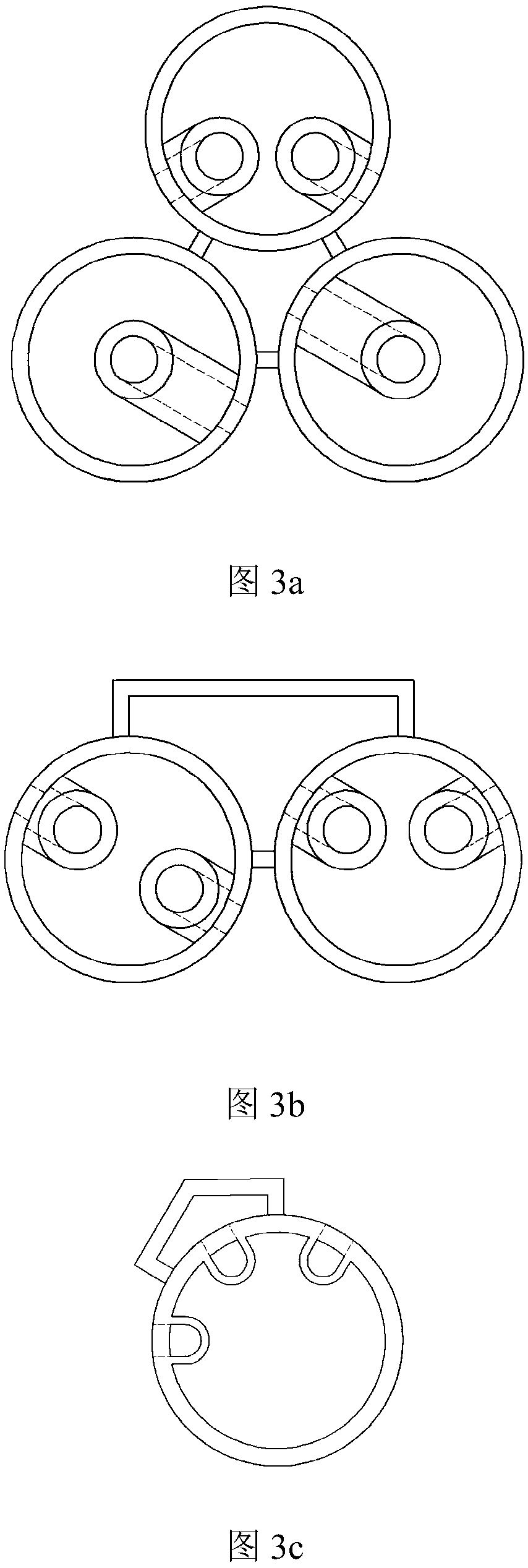

Image

  • Sub-channel flow sampling device and method
  • Sub-channel flow sampling device and method
  • Sub-channel flow sampling device and method

Examples


Embodiment Construction

[0022] Below in conjunction with accompanying drawing and specific embodiment the present invention is described in detail:

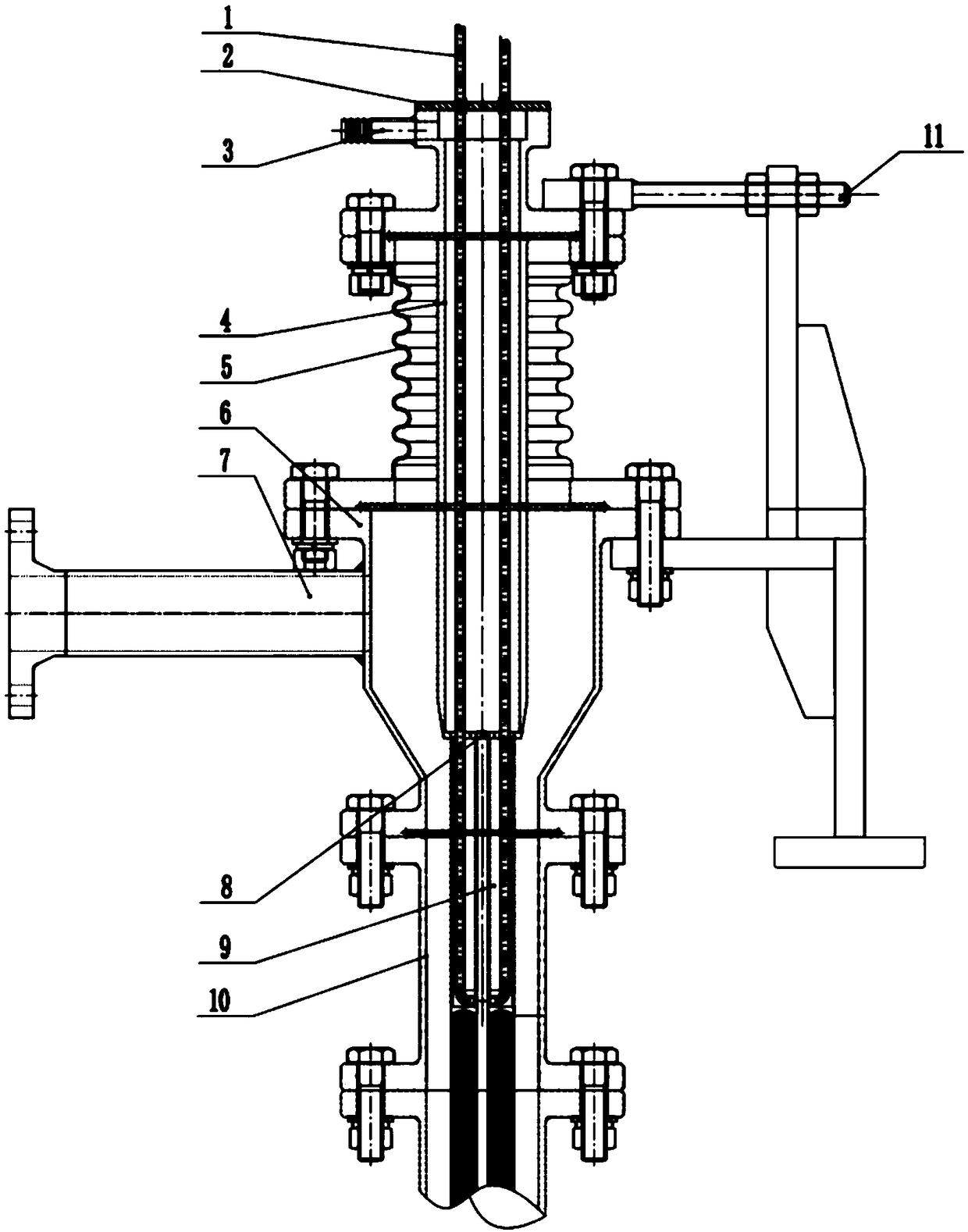
[0023] Such as figure 1 As shown, a sub-channel flow sampling device of the present invention, the flow sampling device is based on the principle of isokinetic sampling, including a pressure introduction tube 1, a cover 2 on the sampling flow channel, a sampling section outlet connecting pipe 3, and a circular cross-section sampling flow channel 4. Flexible bellows 5, upper chamber 6, upper chamber outlet connection 7, lower cover of sampling channel 8, sampling probe 9, visualization pipe section 10, and adjustment device 11.

[0024] The sampling probe 9 is located at the lower part of the entire flow sampling device for extracting the sub-channel flow, and the pressure introduction tube 1 is located inside the sampling probe 9 and welded with the inner tube wall of the sampling probe; the pressure introduction tube 1 is drawn through the inside of th...


PUM


Abstract

Provided is a sub-channel flow sampling device. The device comprises an e-press, a sampling passageway upper sealing cover, a sampling section outlet connecting pipe, a round section sampling passageway, a flexible corrugated pipe, an upper chamber, an upper chamber outlet connecting pipe, a sampling passageway lower sealing cover, a sampling probe, a visible pipe section and an adjusting device,wherein the e-press is welded to a hole in the lower end side face of the sampling probe, the sampling probe is used for measuring the static pressure of an internal sub-channel and an adjacent sub-channel, the round section sampling passageway penetrates through the top of the upper chamber and is connected with the upper chamber through the flexible corrugated pipe. The lower end of the upper chamber is connected with the visible pipe section for observing and calibrating the position of the sampling probe. The adjusting device can adjust the position of the sampling probe. The sampling device is connected with a rod cluster test section through the visible section and connected with a test pipeline system through the sampling section outlet connecting pipe and the upper chamber outlet connecting pipe. The sampling device is simple in overall structure and easy to machine, and a flow sampling scheme is provided for the research on the rod cluster sub-channel flowing characteristic. The invention further provides a use method of the sampling device.

Description

technical field [0001] The invention belongs to the technical field of sampling, and in particular relates to a sub-channel flow sampling device and method. technical background [0002] Typical reactor cores of pressurized water reactors, liquid metal reactors, supercritical water reactors, etc. are composed of hundreds of fuel assemblies, and each fuel assembly is composed of hundreds of fuel elements. In the preliminary thermal design of the core, The single-channel model is commonly used to simulate a single component. In the single-channel model, the channel to be calculated is regarded as isolated and closed, and the exchange of mass, momentum and energy with other channels is not considered in the entire core height. In order to make the calculation more realistic, a more advanced sub-channel model was developed. Sub-channels need to be divided before the analysis of the sub-channel model. The division of sub-channels is artificially stipulated. Usually, the coolant ...

Claims


Application Information

Patent Timeline
Patent Type & Authority Applications(China)
IPC IPC(8): G01F15/00
CPCG01F15/00
Inventor 张大林梁禹秋穗正田文喜苏光辉张魁
Owner XI AN JIAOTONG UNIV
Learn More