
Method for calculating the drift velocity of an ionospheric irregularity based on the phase screen theory

A technology of drift speed and calculation method, applied in the field of ionosphere, can solve the problem of reducing the universality of the method, and achieve the effect of good measurement accuracy

Active Publication Date: 2018-12-07
BEIHANG UNIV
View PDF5 Cites 2 Cited by
  • Summary
  • Abstract
  • Description
  • Claims
  • Application Information

AI Technical Summary

Problems solved by technology

[0005] Carrano, C.S., Groves, K.M., Rino, C.M., Doherty, P.H.(2016).A technique for inferring zonal irregularity drift from singlestation gnss measurements of intensity(s4)and phase(σφ)scintillations.Radio Science,51(8):1263- 1277.) Obtain the zonal drift velocity of ionospheric irregularities mainly through the ground-based GNSS observation network, ground observation radar and ionospheric altimeter; the scholars of Boston College in the United States recently proposed to use the ionospheric scintillation monitor to obtain the ionospheric scintillation Index and navigation observation data to infer the shape of ionospheric irregularities, the method has some enlightenment, but its calculation requires high-frequency (50Hz) original navigation observations, thus reducing the universality of the method

Method used


Image

  • Method for calculating the drift velocity of an ionospheric irregularity based on the phase screen theory
  • Method for calculating the drift velocity of an ionospheric irregularity based on the phase screen theory
  • Method for calculating the drift velocity of an ionospheric irregularity based on the phase screen theory

Examples


Embodiment Construction

[0042] The present invention will be described in detail below with reference to the accompanying drawings and specific embodiments. It should be pointed out that the described embodiments are only intended to facilitate the understanding of the present invention and do not play a limiting role.

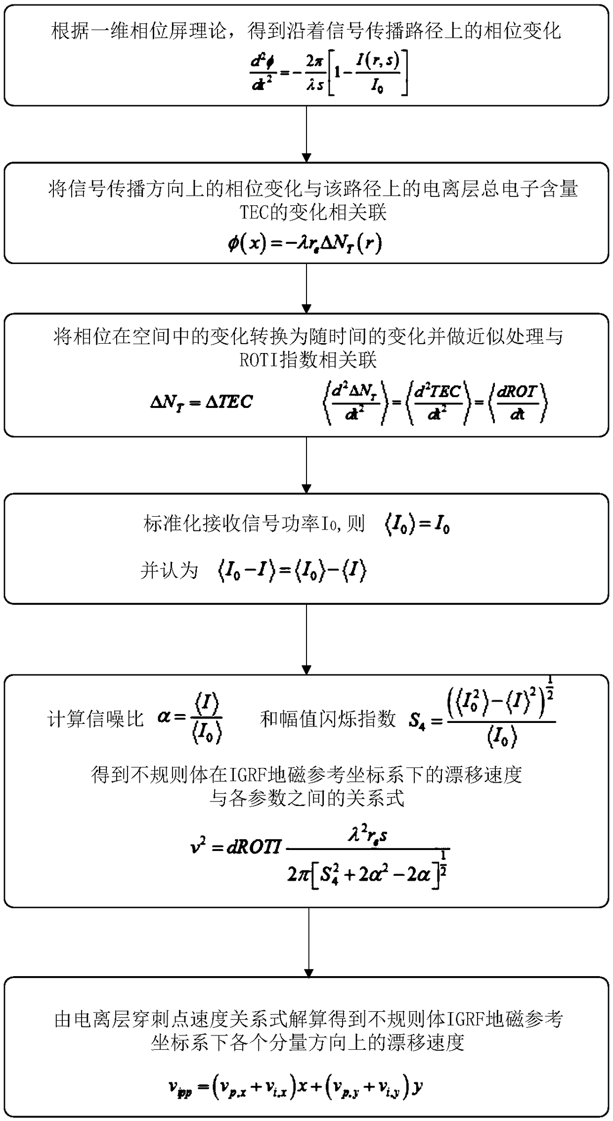
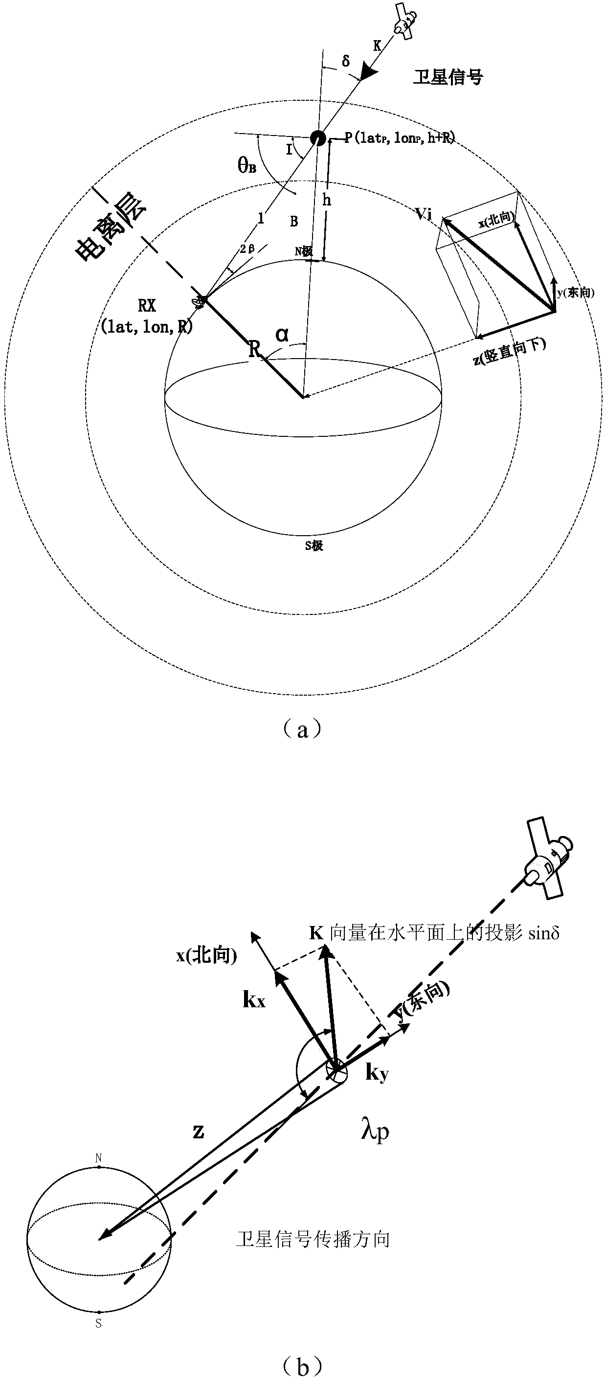
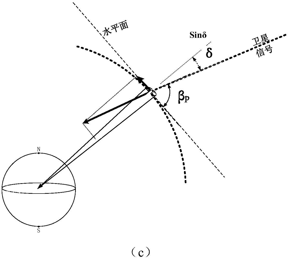
[0043] The present invention proposes a method for calculating the drift velocity of ionospheric irregularities based on the phase screen theory, which describes in detail the drift velocity of ionospheric irregularities and the changes in satellite elevation angle, signal-to-noise ratio, amplitude scintillation index and ROTI The relationship between rates. It can better describe the impact of ionospheric morphology changes on scintillation.

[0044] Such as figure 1 As shown, the specific implementation steps of the present invention are as follows:

[0045] 1. According to the one-dimensional phase screen theoretical model, assuming that the phase change only occurs in the x direction ...


PUM


Abstract

The invention relates to a method for calculating the drift velocity of an ionospheric irregularity based on the phase screen theory. The method includes the following steps: obtaining a relationshipbetween a phase change and a propagation path; at a receiver end, converting the spatial variation of a phase into a relationship between the phase change and the time, and forming association with atime change of ionospheric electron content TEC; associating the time change of the ionospheric electron content TEC with an ROTI index time change rate; on the basis of ionospheric amplitude scintillation indexes and a signal-to-noise ratio, obtaining functional expressions among a time change ratio of the drift velocity of an ionospheric irregularity in an IGRF coordinate and components of the ionospheric irregularity in x and y directions to ROTI, the ionospheric amplitude scintillation indexes, the signal-to-noise ratio and an satellite elevation angle. According to the invention, relations among the time change ratio of the drift velocity of the ionospheric irregularity to ROTI indexes, the ionospheric amplitude scintillation indexes S4, the signal-to-noise ratio and the satellite elevation angle can be obtained. The method realizes in-depth research on a coupling mechanism between the ionospheric irregularity and ionospheric scintillation caused by the ionospheric irregularity.

Description

Technical field [0001] The invention relates to a method for calculating the drift velocity of ionospheric irregular bodies based on phase screen theory, and belongs to the field of ionosphere. Background technique [0002] At present, satellite navigation technology has become an important component of weapons in modern warfare by countries all over the world. The Beidou satellite navigation system is a satellite positioning and navigation system developed and controlled by China itself. It has realized positioning, navigation, timing, and short message services in the Asia-Pacific region; BDS will play a major role in the development of my country's economic, military and society. [0003] The space part of satellite navigation systems is mostly located above 20,000 kilometers, and the transmission of navigation signals passes through the ionosphere, which is inevitably affected by the ionospheric scintillation effect. Ionospheric scintillation affects the propagation of radio w...

Claims


Application Information

Patent Timeline
Patent Type & Authority Applications(China)
IPC IPC(8): G01S19/14
CPCG01S19/14
Inventor 刘杨付连杰李铮
Owner BEIHANG UNIV
Learn More