
Phase-camera-based multi-target reactive voltage coordination control method and system

A camera-tuning, multi-target technology, applied in reactive power adjustment/elimination/compensation, reactive power compensation, electrical components, etc.

Active Publication Date: 2018-12-07
CENT CHINA BRANCH OF STATE GRID CORP OF CHINA +1
View PDF5 Cites 16 Cited by
  • Summary
  • Abstract
  • Description
  • Claims
  • Application Information

AI Technical Summary

Problems solved by technology

[0006] The present invention proposes a multi-objective reactive voltage coordinated control method and system based on the condenser to solve the multi-target reactive voltage coordinated control problem of the condenser in the transient process, transition process and steady state process after a fault

Method used


Image

  • Phase-camera-based multi-target reactive voltage coordination control method and system
  • Phase-camera-based multi-target reactive voltage coordination control method and system
  • Phase-camera-based multi-target reactive voltage coordination control method and system

Examples


Embodiment approach

[0089] Taking the phase regulator project of Shaoshan Converter Station as an example, the specific implementation of the present invention will be further described in detail.

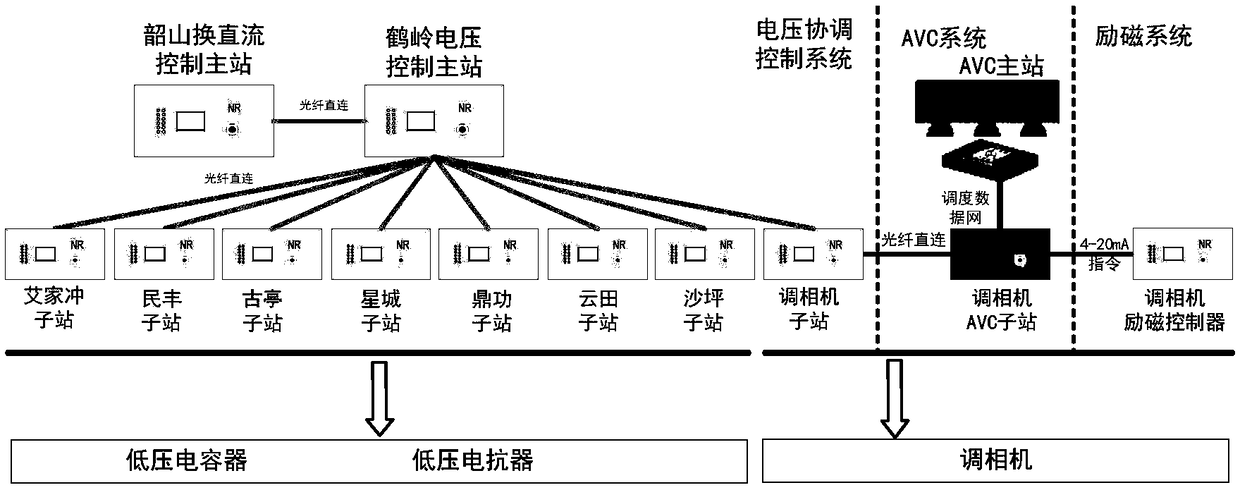
[0090] The multi-objective reactive power and voltage coordinated control system centered on the phase regulator in Shaoshan converter station is composed of three parts: the excitation system of the phase regulator, the voltage coordination control system, and the AVC system. figure 2 shown. Among them, the excitation system of the condenser is integrated into the control system of the condenser, the voltage coordination control system is composed of the relevant substation stability control devices, and the AVC system is composed of the AVC master station at the dispatching end, the condenser and the AVC substation of the near-area plant.

[0091] The excitation system of the condenser adopts the control strategy combining "fast voltage loop + slow reactive loop". The fast voltage loop collects the...


PUM


Abstract

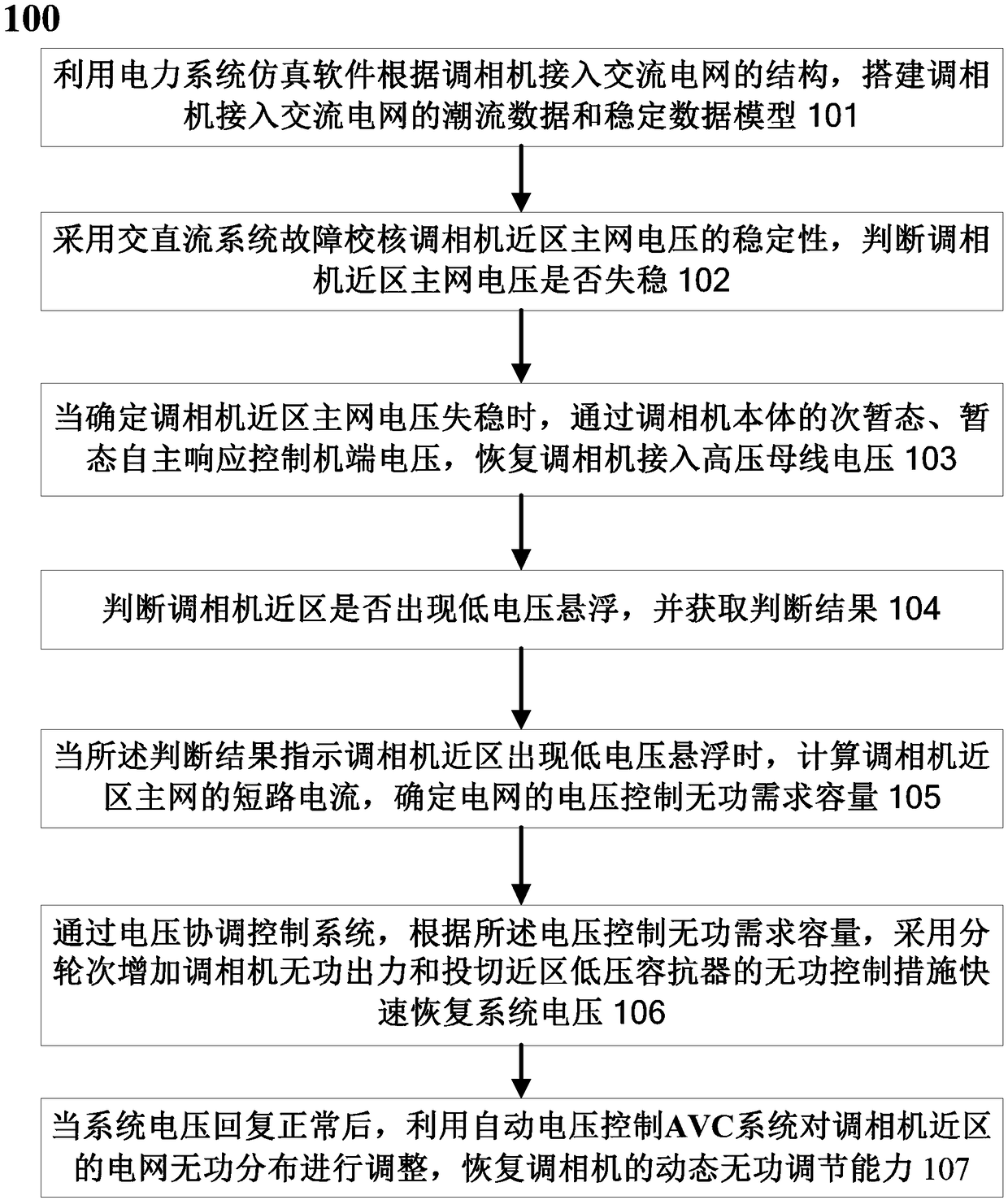
The invention relates to a phase-camera-based multi-target reactive voltage coordination control method and system. The method comprises: power flow data and a stable data model of access to an alternating-current grid by a phase camera are established; fault checking is carried out on stability of a phase camera near-region main grid voltage by using an alternating-current / direct-current system;when instability of the phase camera near-region main grid voltage is determined, the machine-side voltage is controlled by subtranient and transient automatic responses of the phase camera body and access of the phase camera to the high-voltage bus voltage is recovered; whether the near region of the phase camera has low voltage suspension is determined and a determination result is obtained; when the determination result indicates the low voltage suspension in the near region of the phase camera, the short-circuit current of the main gird in the near region of the phase camera is calculatedand the reactive power demand capacity of the voltage control of the grid is determined; the system voltage is restored quickly by employing the reactive power control measures of increasing the reactive output of the phase camera in turn and the near-region low-voltage capacitance of switching in turn; and with the automatic voltage control system, the reactive power distribution of the power grid in the near region of the phase camera is adjusted and the dynamic reactive adjusting capability of the phase camera is restored.

Description

technical field [0001] The present invention relates to the technical field of electric power system, and more specifically, relates to a multi-objective reactive voltage coordinated control method and system based on a condenser. Background technique [0002] In the power system, the synchronous generator is the most common rotating equipment. It can generate reactive power while generating active power, and it is the reactive power source with the best performance. The condenser is a synchronous generator in a special operating state, which retains the good reactive power compensation performance of the synchronous generator without generating active power. [0003] The performance advantage of the condenser is mainly reflected in that it can provide reactive power compensation and voltage support in the transient state, transition process and steady state full time scale. In terms of transient, at the moment when the power grid fails and the voltage drops, the condenser ...

Claims


Application Information

Patent Timeline
IPC IPC(8): H02J3/18H02J3/50
CPCH02J3/1885H02J3/50Y02E40/30
Inventor 申旭辉邵德军马世英徐友平李锴唐晓骏谢岩党杰潘晓杰张三洪罗红梅
Owner CENT CHINA BRANCH OF STATE GRID CORP OF CHINA
Learn More