Circuit structure applied to stabilize output of microgrid energy storage system

An energy storage system and circuit structure technology, which is applied to AC network circuits, circuit devices, battery circuit devices, etc., can solve problems such as the stable current demand that cannot fully meet the large fluctuations of the load, and achieve smooth bus power fluctuations and stable bus bars. effect of current

Active Publication Date: 2018-12-07
HUBEI UNIV OF TECH
View PDF7 Cites 0 Cited by
  • Summary
  • Abstract
  • Description
  • Claims
  • Application Information

AI Technical Summary

Problems solved by technology

[0003] The current traditional method is to use supercapacitors and batteries in parallel to suppress current fluctuations, but supercapaci

Method used


Image

  • Circuit structure applied to stabilize output of microgrid energy storage system
  • Circuit structure applied to stabilize output of microgrid energy storage system
  • Circuit structure applied to stabilize output of microgrid energy storage system

Examples


Embodiment Construction

[0027] In order to facilitate those of ordinary skill in the art to understand and implement the present invention, the present invention will be described in further detail below in conjunction with the examples. It should be understood that the implementation examples described here are only used to illustrate and explain the present invention, and are not intended to limit the present invention.

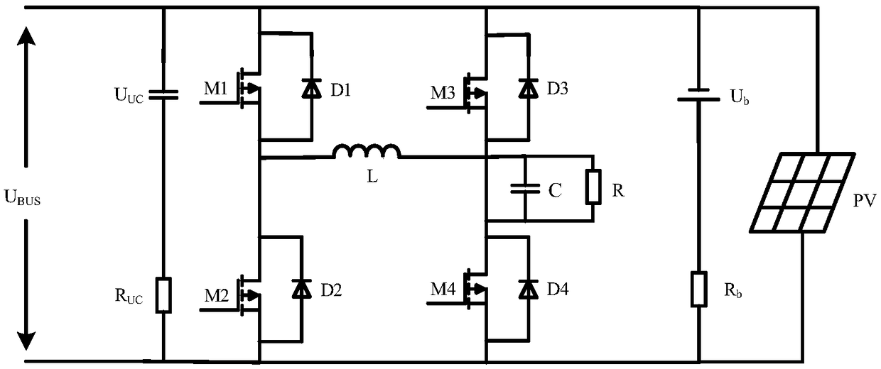
[0028] figure 1 It is a schematic diagram of the circuit topology of the present invention, mainly including an inductor L, a capacitor C, a resistor R, a photovoltaic panel PV, a supercapacitor (U UC , R UC ), a storage battery (U b , R b ), four diodes (D1, D2, D3, D4), four switch tubes (M1, M2, M3, M4), the connection diagram of each original is as follows figure 1 shown. in:

[0029] (1) Photovoltaic panel PV and supercapacitor U UC and R UC parallel connection;

[0030] (2) Photovoltaic panel PV and battery U b and R b parallel connection;

[0031] (3) The photovo...


PUM


Abstract

The invention relates to a circuit structure applied to stabilize the output of a microgrid energy storage system. The circuit comprises an inductor L, a capacitor C, a resistor R, a photovoltaic panel PV, a supercapacitor (UUC, RUC), a storage battery (Ub, Rb), four diodes (D1, D2, D3, and D4) and four switch tubes (M1, M2, M3, and M4). A circuit is connected in series and works in a microgrid. When an energy storage battery is in a charging state, the switch tubes M2 and M3 cut off, the switch tubes M1 and M4 are conducted, and a photovoltaic power generation system and a power grid charge the energy storage system. When the energy storage battery is in a discharging state, the switch tubes M2 and M3 are conducted, the switch tubes M1 and M4 cut off, and the energy storage system discharges a load. Compared with a previous microgrid energy storage system, by using the circuit structure of the invention, a response speed is fast, a photovoltaic battery output fluctuation caused by anenvironment change can be stabilized, and a bus power sudden change caused by a load change can be restrained.

Description

technical field [0001] The invention belongs to the technical field of microgrid energy storage, and in particular relates to an H-bridge DC-DC converter structure. Background technique [0002] Photovoltaic power generation is seriously affected by the environment, and the power generation is low on cloudy days and nights, so it cannot continuously supply power to the load. In addition, when the load power mutation in the microgrid is large, only the instantaneous action of the supercapacitor cannot quickly and effectively stabilize the bus voltage and current. Therefore, in order to prevent the rapid drop of the DC bus current caused by the above problems and ensure the stability of the output power of the system, it is necessary to take measures to quickly and effectively weaken or suppress power fluctuations. [0003] The current traditional method is to use supercapacitors and batteries in parallel to suppress current fluctuations, but supercapacitors are limited by th...

Claims


Application Information

Patent Timeline
IPC IPC(8): H02J3/24H02J3/38H02J3/28H02J3/32H02J7/34
CPCH02J3/383H02J3/24H02J3/28H02J3/32H02J7/345Y02E70/30Y02E10/56
Inventor 徐元中肖菀莹吴铁洲熊金龙
Owner HUBEI UNIV OF TECH
Why Eureka
Try Eureka