
Patient and equipment shifting device

A mobile device and patient technology, applied in surgical equipment, transportation and packaging, appliances to help people move around, etc., can solve the problems of high equipment maintenance requirements, excess cost, complicated operation, etc., and achieve compact structure design, convenient storage, mobile good effect

Pending Publication Date: 2018-12-11
凯泰科(中国)医疗器械股份有限公司
View PDF0 Cites 6 Cited by
  • Summary
  • Abstract
  • Description
  • Claims
  • Application Information

AI Technical Summary

Problems solved by technology

The walker is generally equipped with a seat and the bottom is equipped with wheels to facilitate movement. To expand the function of the walker, it is usually possible to add components such as infusion equipment, drainage equipment, oxygen tanks, and auxiliary handles, which are practical. At the same time, they can Mobile operation is convenient to use and operate during patient transfer, but there are also some shortcomings. If the above-mentioned newly added components are always installed on the walker, it will appear cumbersome. At the same time, for patients who only need a single walker to assist walking , it is superfluous and costly; if the above-mentioned newly added components are transferred from the existing bracket to the walker for temporary assembly, once the patient arrives at a certain position, the newly added components will be unloaded and transferred to the original position, which will be cumbersome to operate , high maintenance requirements for equipment

Method used


Image

  • Patient and equipment shifting device
  • Patient and equipment shifting device
  • Patient and equipment shifting device

Examples

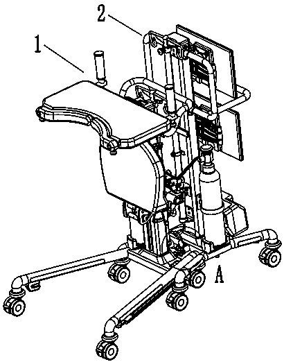
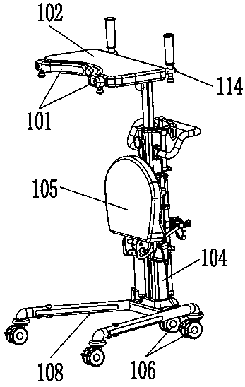
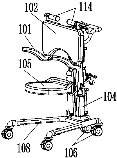

Embodiment Construction

[0025] The following will describe in detail with reference to the accompanying drawings in conjunction with the embodiments, so as to further explain the technical features and advantages of the present invention.

[0026] Such as Figure 1-9 As shown, a patient and equipment moving device of the present invention includes a movable patient transfer rack 1 and an equipment rack 2, and the patient transfer rack 1 and the equipment rack 2 are fixedly connected by an automatic locking assembly, and the automatic locking assembly includes a fixed The connecting piece 107 on the patient transfer frame 1 and the bent plate 4 fixed on the equipment frame 2, the opening on the connecting piece 107 is snapped and connected with the pin 8 provided on the bent plate 4, and the patient transfer The frame 1 includes a support frame 104 , a rotatable seat 105 and an armrest-back assembly 102 installed on the support frame 104 , and the equipment frame 2 includes a frame 206 and a battery p...


PUM


Abstract

The invention discloses a patient and equipment shifting device which comprises a movable patient transfer frame and an equipment frame. The patient transfer frame is fixedly connected with the equipment frame by an automatic locking assembly, the automatic locking assembly comprises a connecting sheet and a bent plate, the connecting sheet is fixed onto the patient transfer frame, the bent plateis fixed onto the equipment frame, open holes in the connecting sheet are fastened and connected with dowels arranged on the bent plate, the bent plate can rotate a fixing rod which is used as a fulcrum, a spring is further arranged at an end of the bent plate, the patient transfer frame comprises a support frame, a rotatable seat and an armrest and backrest assembly, the seat and the armrest andbackrest assembly are mounted on the support frame, the equipment frame comprises a bracket and a storage battery pack mounted at the bottom of the bracket, the storage battery pack is mounted on bases, USB (universal serial bus) jacks and power line jacks are formed in the storage battery pack, the bracket is fixed onto the bases, and wheels are mounted under the bases. The patient and equipmentshifting device has the advantages that the patient and equipment shifting device can be used as a wheelchair or a walking aid, and is easy to position, small in occupied space and convenient to move,and nesting can be facilitated.

Description

technical field [0001] The invention relates to the technical field of improved design of medical equipment, in particular to a patient and equipment moving device. Background technique [0002] For the elderly and people with walking disabilities, due to their limited mobility, they need assistive tools such as walkers to provide proper support and obtain proper rest when moving. The walker is generally equipped with a seat and the bottom is equipped with wheels to facilitate movement. To expand the function of the walker, it is usually possible to add components such as infusion equipment, drainage equipment, oxygen tanks, and auxiliary handles, which are practical. At the same time, they can Mobile operation is convenient to use and operate during patient transfer, but there are also some shortcomings. If the above-mentioned newly added components are always installed on the walker, it will appear cumbersome. At the same time, for patients who only need a single walker to...

Claims


Application Information

Patent Timeline
Patent Type & Authority Applications(China)
IPC IPC(8): A61H3/04A61G5/08A61G5/10A61B50/13
CPCA61B50/13A61G5/0875A61G5/10A61H3/04
Inventor 丰丽
Owner 凯泰科(中国)医疗器械股份有限公司
Learn More