

Atomization air purifier
A technology for atomizing air and air purification, applied in chemical instruments and methods, using liquid separation agents, separation devices, etc., can solve the problems of high price, complicated installation, air pollution, etc., and achieve the effect of easy cleaning
- Summary
- Abstract
- Description
- Claims
- Application Information
AI Technical Summary
Problems solved by technology
Method used
Image

Examples
Embodiment
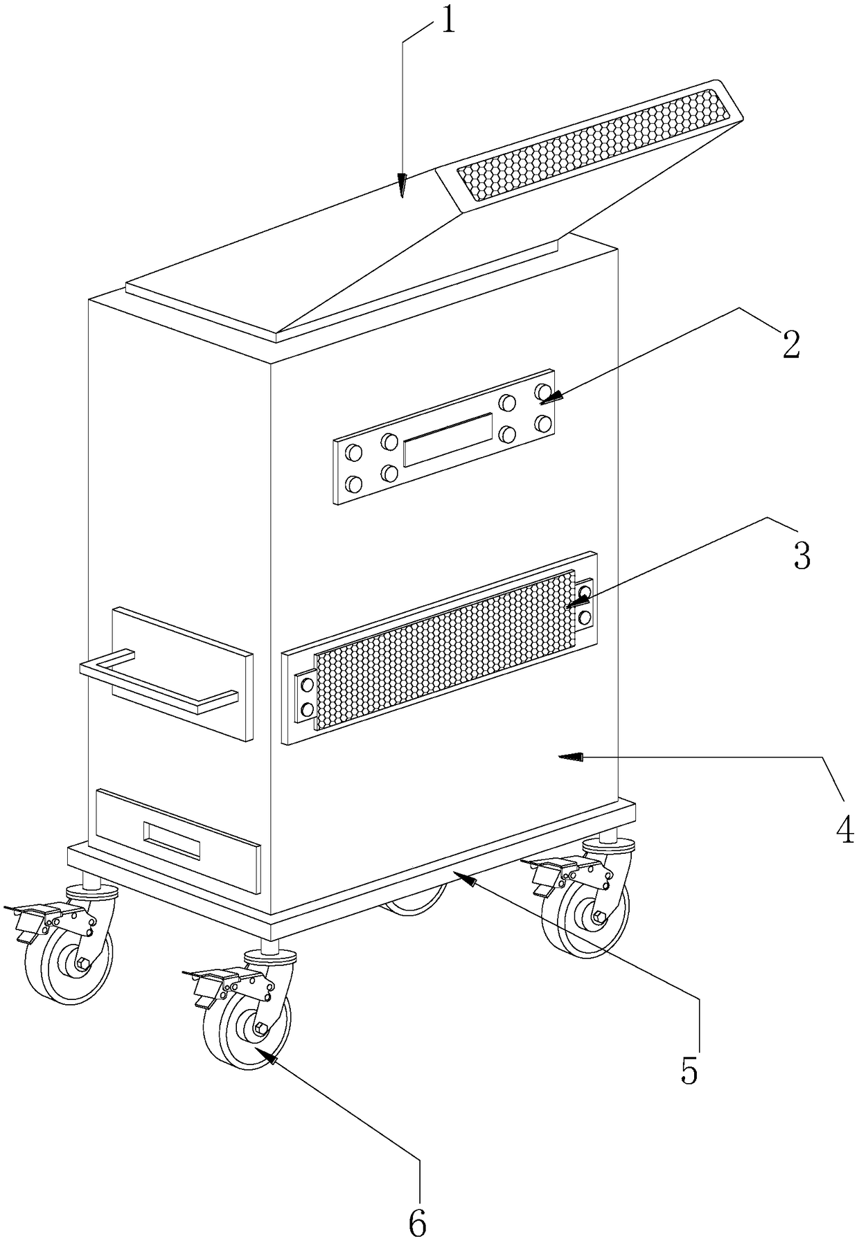
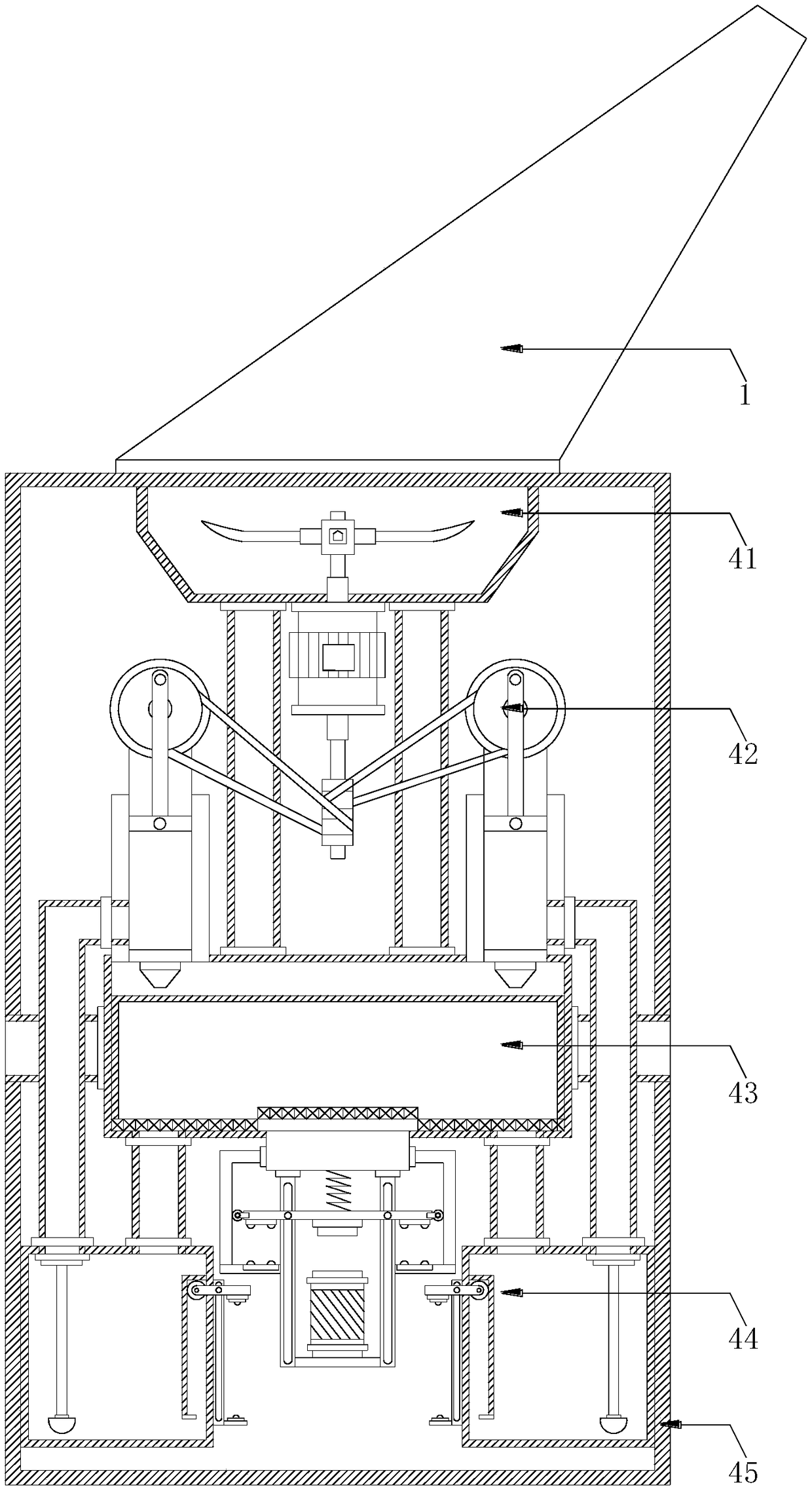
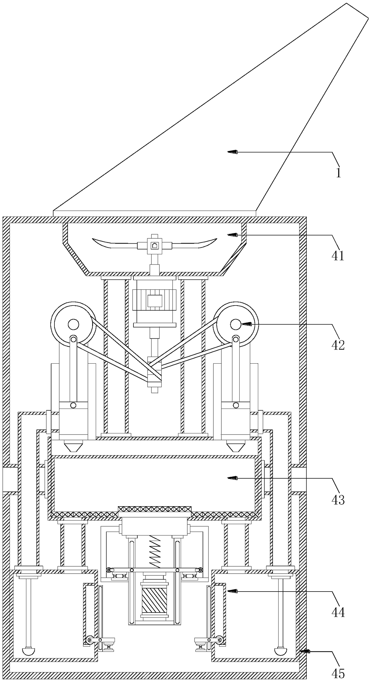
[0024] see Figure 1-Figure 5 , the present invention provides an atomizing air purifier, the structure of which includes an air intake duct 1, a control panel 2, an air outlet filter water screen cover 3, an atomizing air purification device 4, a bottom frame 5, and swivel casters 6. The bottom Four swivel casters 6 are evenly spaced at the bottom of the frame 5, and the swivel casters 6 are screwed to the bottom frame 5, and the top of the bottom frame 5 is provided with an atomizing air purification device 4 and the two are interlocked. , the front and rear ends of the atomized air purification device 4 are provided with an air outlet water filter screen cover 3, and the described air outlet water filter screen cover 3 is fixed on the surface of the atomization air purification device 4 by screws, and the described The top of the atomizing air purification device 4 is provided with an air intake duct 1 and the two adopt an interference fit. A control panel 2 is provided bel...
PUM
 Abstract
Description
Claims
Application Information