Rapid and efficient feed stirring equipment

A high-efficiency technology for feed mixing, applied in feed, mixer accessories, mixers with rotary mixing devices, etc., can solve the problems of limiting fish feed production, reducing farmers' income, and consuming a lot of physical strength, and improving the efficiency of feed mixing. The effect of speeding up the feed mixing process and improving the operation efficiency

Inactive Publication Date: 2018-12-11
金华市邀特科技有限公司
View PDF5 Cites 3 Cited by
  • Summary
  • Abstract
  • Description
  • Claims
  • Application Information

AI Technical Summary

Problems solved by technology

[0003] However, it takes a lot of physical strength to mash and mix the materials when preparing fish feed by yourself, and it takes too much time. In addition, fish feed can only be prepared in a small amount at a time, which limits the efficiency of fish feed preparation and the output of fish feed , which indirectly reduces the income of farmers

Method used


Image

  • Rapid and efficient feed stirring equipment
  • Rapid and efficient feed stirring equipment
  • Rapid and efficient feed stirring equipment

Examples


Embodiment 1

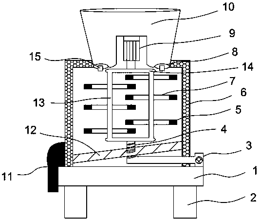
[0023] Such as Figure 1-2 As shown, the fast and efficient feed mixing equipment includes a base 1, the lower end of the base 1 is provided with a foot 2, the upper end of the base 1 is connected to a housing 6, the lower side of the housing 6 is provided with a discharge port 11, and the upper end of the housing 6 is connected to the falling The lower side of the material box 10 is connected, and the middle end of the bottom of the blanking box 10 is concave, and is fixedly connected with the middle part of the biaxial output motor 9, and the output shaft at the lower end of the biaxial output motor 9 is connected to the linkage rod 14, and the bottom of the linkage rod 14 is vertical respectively. Stirring shafts 13 are connected, and stirring rods 7 arranged horizontally are alternately and evenly distributed on the stirring shafts 13 at both ends. The feed mixing equipment sets a base under the shell, and the shell can be stably fixed above the base, so that when the feed...

Embodiment 2

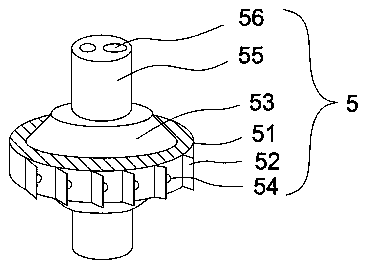
[0028] Such as Figure 3-4 As shown, the optimization scheme of this embodiment on the basis of Embodiment 1 is: the linkage rod 14, the stirring rod 7, and the stirring shaft 13 are hollow built in, and the rotating cleaning device 5 is installed at both ends of the stirring rod 7, and the rotating cleaning device 5 includes Cleaning disc 51, the upper and lower ends of cleaning disc 51 are equipped with mutually symmetrical round platform 53, the upper surface of round platform 53 is provided with connecting column 55, the inside of connecting column 55 is provided with two through holes 56 of different sizes, the axis of through hole 56 and the connecting column 55 axes are parallel, one end of the two through holes 56 communicates with the hollow structure of the stirring rod 7, and the other end of the two through holes 56 communicates with the symmetrical two spiral passages 16 in the round platform 53 respectively, and the spiral passages 16 are connected with the two bu...

Embodiment 3

[0032] Such as Figure 5-6 As shown, the optimization scheme of this embodiment on the basis of Embodiment 1 is: the middle end of the bottom of the blanking box 10 is provided with an inwardly concave concave surface 23, and the output shaft at the upper end of the biaxial output motor 9 passes through the concave surface 23 and the blanking box The connecting rod 25 arranged horizontally in 10 is connected, and a group of runners 28 are respectively connected to the bottom of the two ends of the connecting rod 25. Every two runners 28 parallel up and down constitute a group. The runners 28 are provided with crushing teeth 27, and the crushing teeth 27 Cooperate with the tooth grooves 24 provided below the two ends of the inner concave surface 23 of the blanking box 10 . By setting a runner inside the blanking box, the crushing teeth are evenly distributed on the runner, and driven by the micro motor, the runner can preliminarily grind the feed in the blanking box, so that th...


PUM


Abstract

The invention discloses rapid and efficient feed stirring equipment. The rapid and efficient feed stirring equipment comprises a base; a lower end of the base is provided with support legs; a shell isconnected to an upper end of the base; a discharge port is disposed at the downside of the shell; an upper end of the shell is connected with a lower side surface of a blanking box; a middle end of the bottom of the blanking box is in a recessed shape and is fixedly connected with a middle part of a two-shaft output motor; an output shaft at a lower end of the two-shaft output motor is connectedwith a linkage rod; a stirring shaft is respectively and vertically connected to lower parts of two ends of the linkage rod; stirring rods which are disposed horizontally are uniformly distributed onthe stirring shafts at two ends in a staggered manner. Through the disposed linkage rod, the feed stirring equipment can do a circular movement under rotation of the two-shaft output motor so that thetwo stirring shafts vertically connected to the lower parts of the two ends of the linkage rod rotate correspondingly and the stirring rods disposed on the stirring shafts respectively and alternately stir feeds, thus the feed stirring process is accelerated, the feed stirring efficiency is improved and the feed stirring is more uniform.

Description

technical field [0001] The invention relates to the field of aquaculture, in particular to fast and efficient feed mixing equipment. Background technique [0002] Fish feed, as the name suggests, is feed for fish. Its main components are protein, fat, vitamins and minerals. Protein is an important nutrient for fish and shrimp to survive, and is an important component of body cells, tissues and organs. Fish Normal growth requires protein in sufficient quantity, easy to digest and absorb, and suitable ratio of various amino acids in the feed. When the fish intake of protein is insufficient, the growth will be slow, the body's immunity will decline, and the protein with appropriate ratio of various amino acids will be consumed by fish. When it is insufficient, the growth will be slow, the body's immunity will be reduced, the tissue renewal will be slow, the wound healing will be poor, and it will be prone to diseases. Therefore, many farmers will prepare corresponding fish feed...

Claims


Application Information

Patent Timeline
Patent Type & Authority Applications(China)
IPC IPC(8): B01F7/16B01F7/18B01F15/00A23N17/00
CPCA23N17/007B01F27/85B01F27/90B01F35/53B01F2101/18
Inventor 林媛
Owner 金华市邀特科技有限公司
Why Eureka
Try Eureka