
Internal driving type mucilage printing and flocking rail system

A technology of internal drive and transmission track, which is applied in printing, printing machines, printing technology, etc., can solve the problems of low work efficiency and complicated process, and achieve the effect of high work efficiency, simple process and high precision

Active Publication Date: 2018-12-11
WUHAN TEXTILE UNIV
View PDF7 Cites 3 Cited by
  • Summary
  • Abstract
  • Description
  • Claims
  • Application Information

AI Technical Summary

Problems solved by technology

[0007] The purpose of the present invention is to overcome the defects and problems of complex process and low work efficiency in the prior art, and provide an internally driven rubber flocking track system with simple process and high work efficiency

Method used


Image

  • Internal driving type mucilage printing and flocking rail system
  • Internal driving type mucilage printing and flocking rail system
  • Internal driving type mucilage printing and flocking rail system

Examples


Embodiment 1

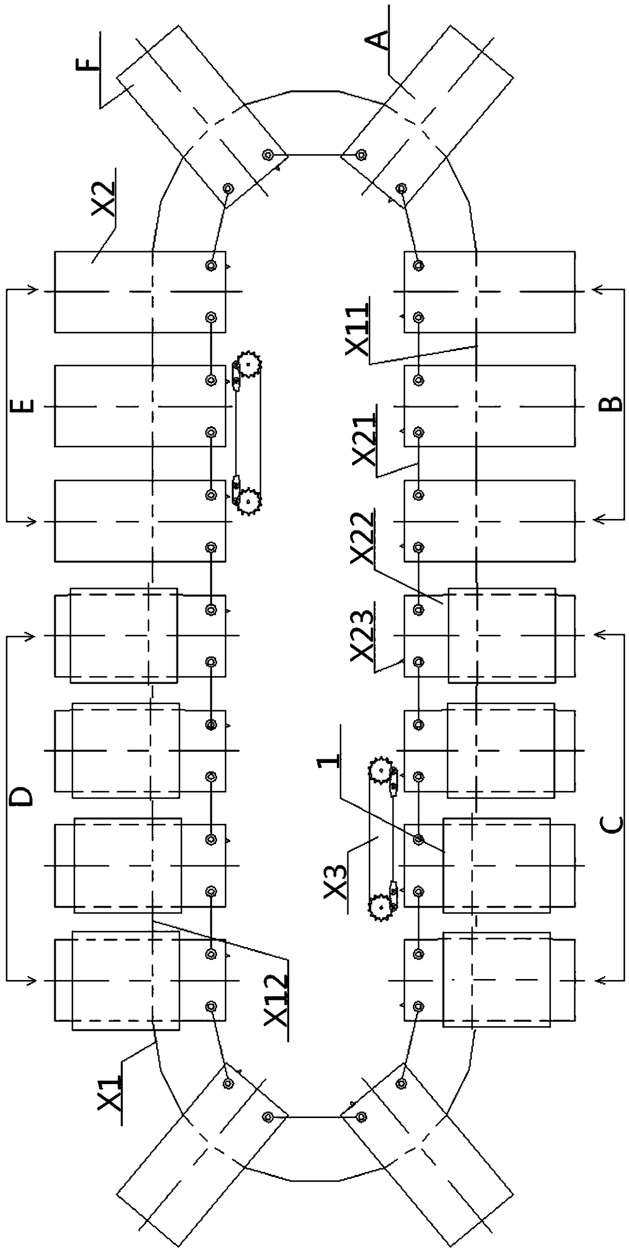
[0060] see Figure 1 to Figure 14 , an internal drive type printing glue flocking track system, including a transmission track X1 and a spreading station A, a printing elastic glue station, a flocking station E and a cloth receiving station F arranged on the transmission track X1, the transmission track X1 is a closed ring structure. The spreading station A, printing elastic glue station, flocking station E, and cloth receiving station F all include at least one table X2, and the bottoms of all table X2 are connected to the transmission The top of the track X1 is slidably fitted, and the adjacent platen X2 is connected by a connecting rod X21; the track system also includes a printing release agent station B and at least one platen driving device X3, and the printing force The rubber station includes the upper station C of the rubber printing and the lower station D of the rubber printing. The printing release agent station B, the upper station C of the rubber printing, and th...

Embodiment 2

[0062] Basic content is the same as embodiment 1, the difference is:

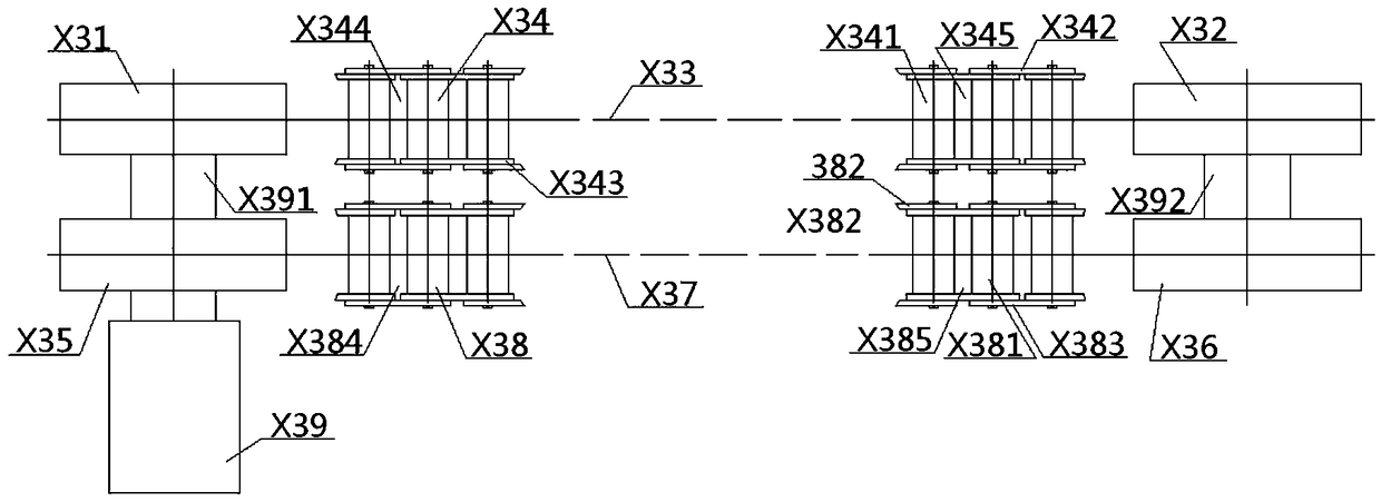
[0063] The platen driving device X3 includes an upper left sprocket X31, an upper right sprocket X32 and an upper chain X33, the upper left sprocket X31 and the upper right sprocket X32 are smooth toothless sprockets, and the upper chain X33 The left and right ends of the chain are respectively wound around the outer periphery of the upper left sprocket X31 and the upper right sprocket X32; the upper chain X33 is a ring structure, including a plurality of upper chain shaft groups X34 with the same structure, and the adjacent upper chain shaft groups The top and bottom ends of X34 are respectively connected by upper and lower group plates X342 and upper and lower group plates X343. There is an upper group gap X344 between adjacent winding shaft groups X34. One winding shaft X341 includes two parallel winding shafts. shaft X341, the upper chain shaft X341 is a vertical column structure, there is an upper shaf...

Embodiment 3

[0066] Basic content is the same as embodiment 1, the difference is:

[0067] A screen frame 1 is arranged directly above the platen X2 in the upper printing station C and the lower printing station D, and a scraper 2 connected to the scraper seat plate 4 is arranged directly above the screen frame 1 , second scraper 3, the left side of described screen frame 1 is connected with the bottom of left vertical board 71, and the top of left vertical board 71 is vertically connected with the inner side of left horizontal board 72, and the top surface of left horizontal board 72 is connected with The bottom of the left vertical adjustment device 7 of the screen frame is connected, the right side of the screen frame 1 is superimposed and connected with the top surface of the lower right horizontal plate 81, and the right side of the lower right horizontal plate 81 is connected with the bottom of the right vertical plate 82 Vertically connected, the top of the right vertical plate 82 i...


PUM


Abstract

The invention relates to an internal driving type mucilage printing and flocking rail system. The internal driving type mucilage printing and flocking rail system comprises a traditional rail and cloth laying stations, release agent printing stations, upper mucilage printing stations, lower mucilage printing stations, flocking stations and cloth clothing stations which are sequentially arranged along the traditional rail and connected; platen drive devices are arranged on front straight rail side where the release agent printing stations and the upper mucilage printing stations are located andon the inner side of the rear straight rail side where the lower mucilage printing stations and the flocking stations are located and are parallel with the straight rail sides, each station comprisesat least one platen, a screen frame is arranged right above each platen in the upper mucilage printing stations and the lower mucilage printing stations, screen frame longitudinal adjusting devices are connected to the left side and the right side of each screen frame, a first scraper and a second scraper which are connected with a scraper base plate are arranged above each screen frame, and thetop of each scraper base plate is connected with transverse and longitudinal displacement devices. The internal driving type mucilage printing and flocking rail system has the advantages that the system is simple in procedures, high in work efficiency, good in platen transmission accuracy, good in printing quality, high in printing efficiency, high in adjustability and wide in application range, and the platens and connecting rods can be well coordinated.

Description

technical field [0001] The invention relates to a device for printing glue and flocking on fabrics, belonging to the field of textile machinery, in particular to an internally driven glue printing and flocking track system, which is particularly suitable for simplifying procedures and improving work efficiency. Background technique [0002] At present, most of the equipment for printing glue and flocking on fabrics first prints glue on the fabric to be treated, and then performs flocking. The glue printing and flocking operations are carried out continuously. The screen printing process in the prior art is relatively complicated, and there are many stations. In order to improve work efficiency, the transmission track in the screen printing process is generally set as an elliptical track or a circular track in the prior art, wherein the circular track drives It is simple, but the station is fixed and cannot be added at will. The elliptical orbit drive is more complicated, but...

Claims


Application Information

Patent Timeline
Patent Type & Authority Applications(China)
IPC IPC(8): B41F15/12B41F15/18B41F15/44B41F15/36B05C19/00
CPCB05C19/001B41F15/12B41F15/18B41F15/36B41F15/44B41P2215/50
Inventor 张智明陈振徐巧梅顺齐姬巧玲肖人彬
Owner WUHAN TEXTILE UNIV
Learn More