Steel pipe concrete column ring beam joint and steel bar binding construction method thereof

A technology for binding concrete-filled steel tube columns and steel bars, which is applied in construction and building structures, etc., can solve problems such as the difficulty in processing and binding steel bars, increasing the difficulty of hooping, and the difficulty in binding ring beams, etc., so as to reduce the processing and The difficulty of binding construction, reducing the difficulty of connection construction, and optimizing the effect of the overall construction process

Pending Publication Date: 2018-12-11
THE FIRST COMPARY OF CHINA EIGHTH ENG BUREAU LTD
View PDF16 Cites 1 Cited by
  • Summary
  • Abstract
  • Description
  • Claims
  • Application Information

AI Technical Summary

Problems solved by technology

Usually the design is copied from the design specification, and it is difficult to process and bind steel bars during on-site construction, which wastes manpower and material resources and is difficult to realize
[0003] The design scheme for the binding of steel bars at ring beam nodes in the prior art is as attached figure 1 As shown, the numbers in the figure respectively indicate 1. CFST column, 2. Ring beam main reinforcement, 3. Structural beam, 4. Ring beam stirrup, and have the following characteristics: 1) The ring beam main reinforcement is connected by welding; 2) Ring The beam stirrup adopts closed stirrups; 3) The main reinforcement of the straight reinforced concrete beam connected to the ring beam is anchored by 90° bending; the construction method is: 1) The main reinforcement of the ring beam is processed by manual bending, and the reinforcement is difficult to process and the processing error is relatively large. 2) The ring beam stirrups are closed hoops, and the on-site jacket is used during construction, which makes it more difficult to cover the stirrups, and because the stirrups are dense, many stirrups cannot be put on; 3) The straight reinforced concrete beam connected to the ring beam It is very difficult for the main reinforcement to be placed in the ring beam before the ring beam reinforcement is bound. After the ring beam reinforcement is bound, it will be anchored. The main reinforcement of the reinforced concrete beam cannot be anchored due to the long bending and straight section.

Method used


Image

  • Steel pipe concrete column ring beam joint and steel bar binding construction method thereof
  • Steel pipe concrete column ring beam joint and steel bar binding construction method thereof
  • Steel pipe concrete column ring beam joint and steel bar binding construction method thereof

Examples


Embodiment Construction

[0045] In order to enable those skilled in the art to better understand the solutions of the present invention, the present invention will be further described in detail below in conjunction with specific embodiments. Apparently, the described embodiments are only some of the embodiments of the present invention, but not all of them. Based on the embodiments of the present invention, all other embodiments obtained by persons of ordinary skill in the art without making creative efforts belong to the protection scope of the present invention.

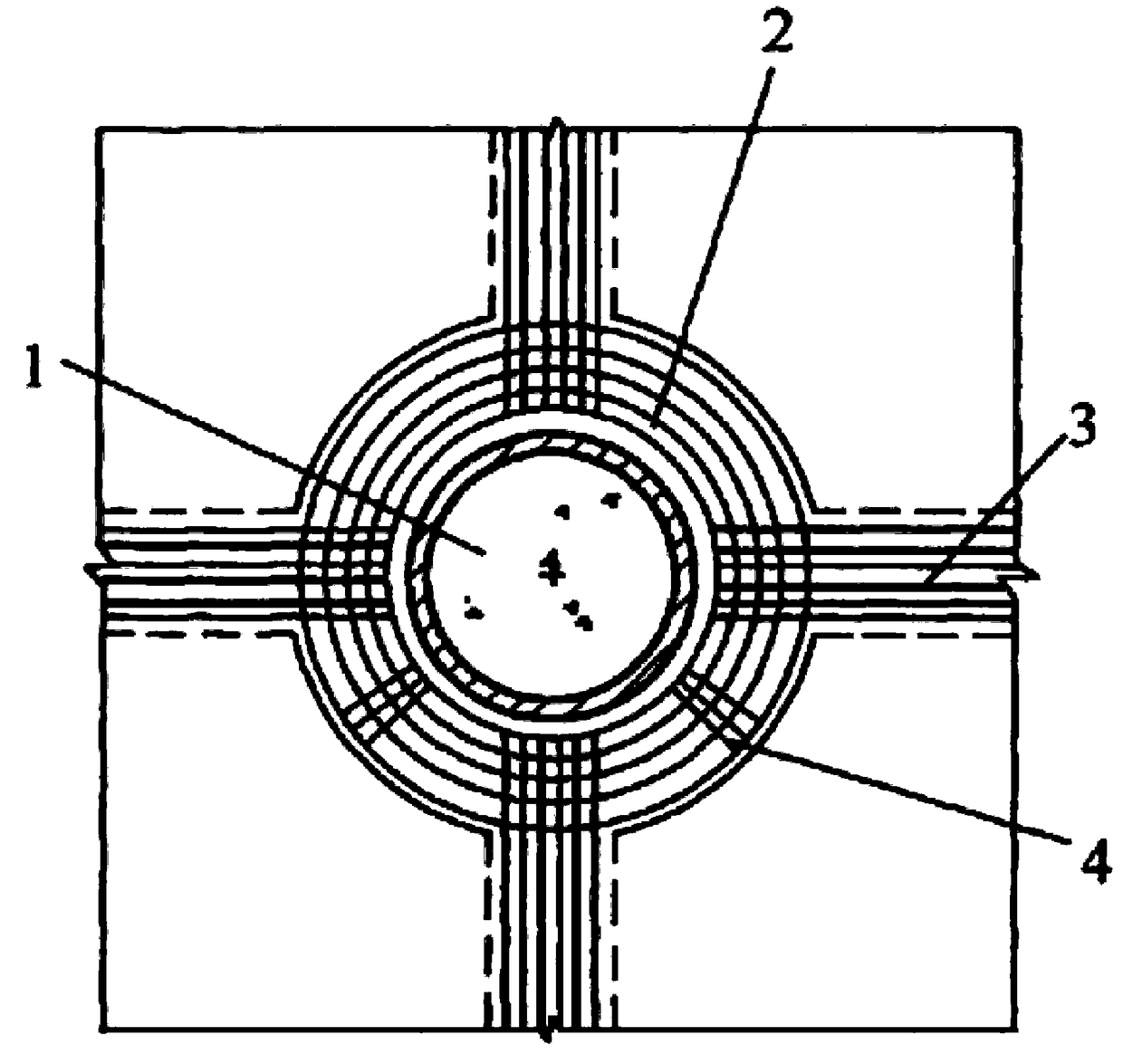
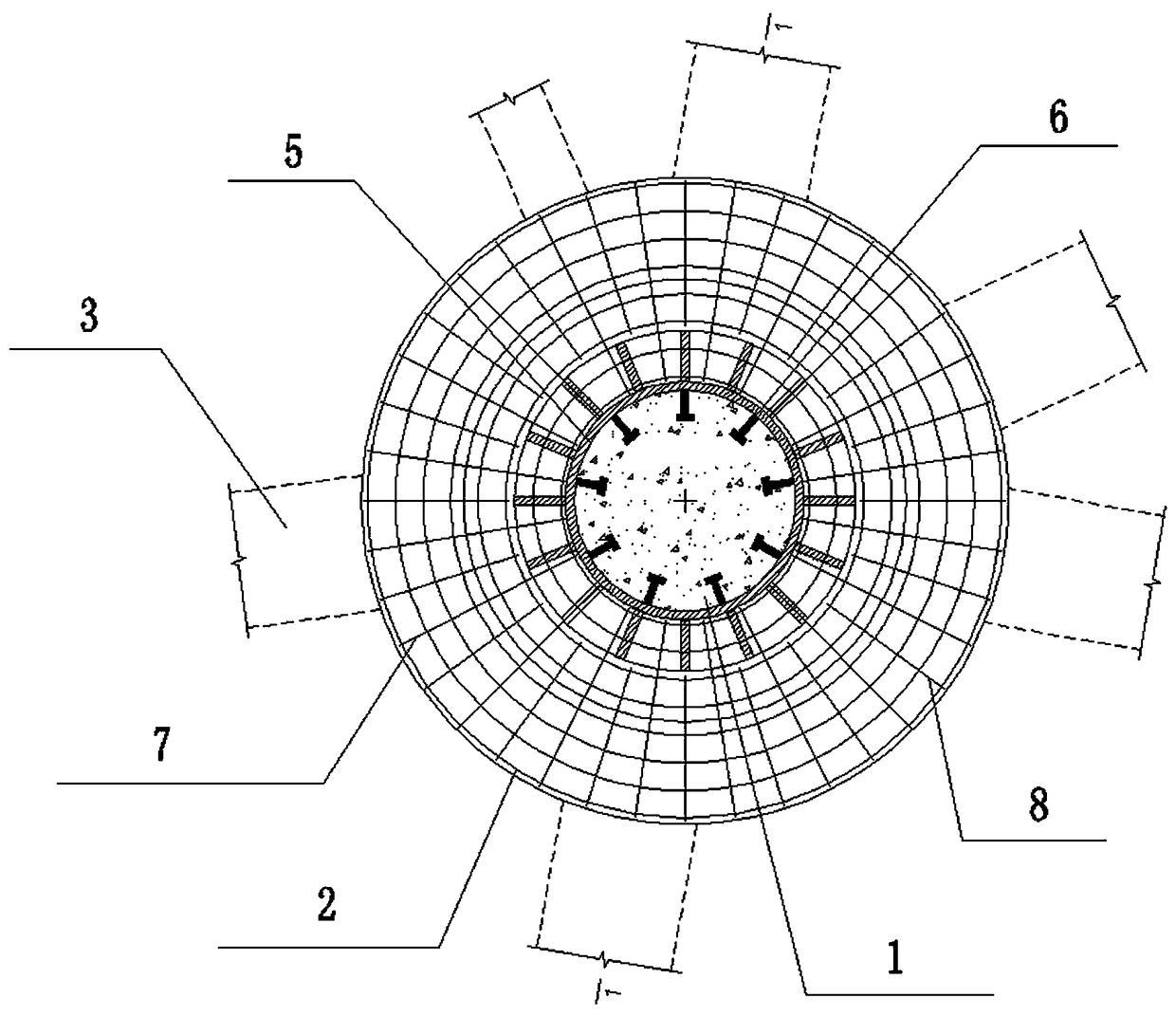
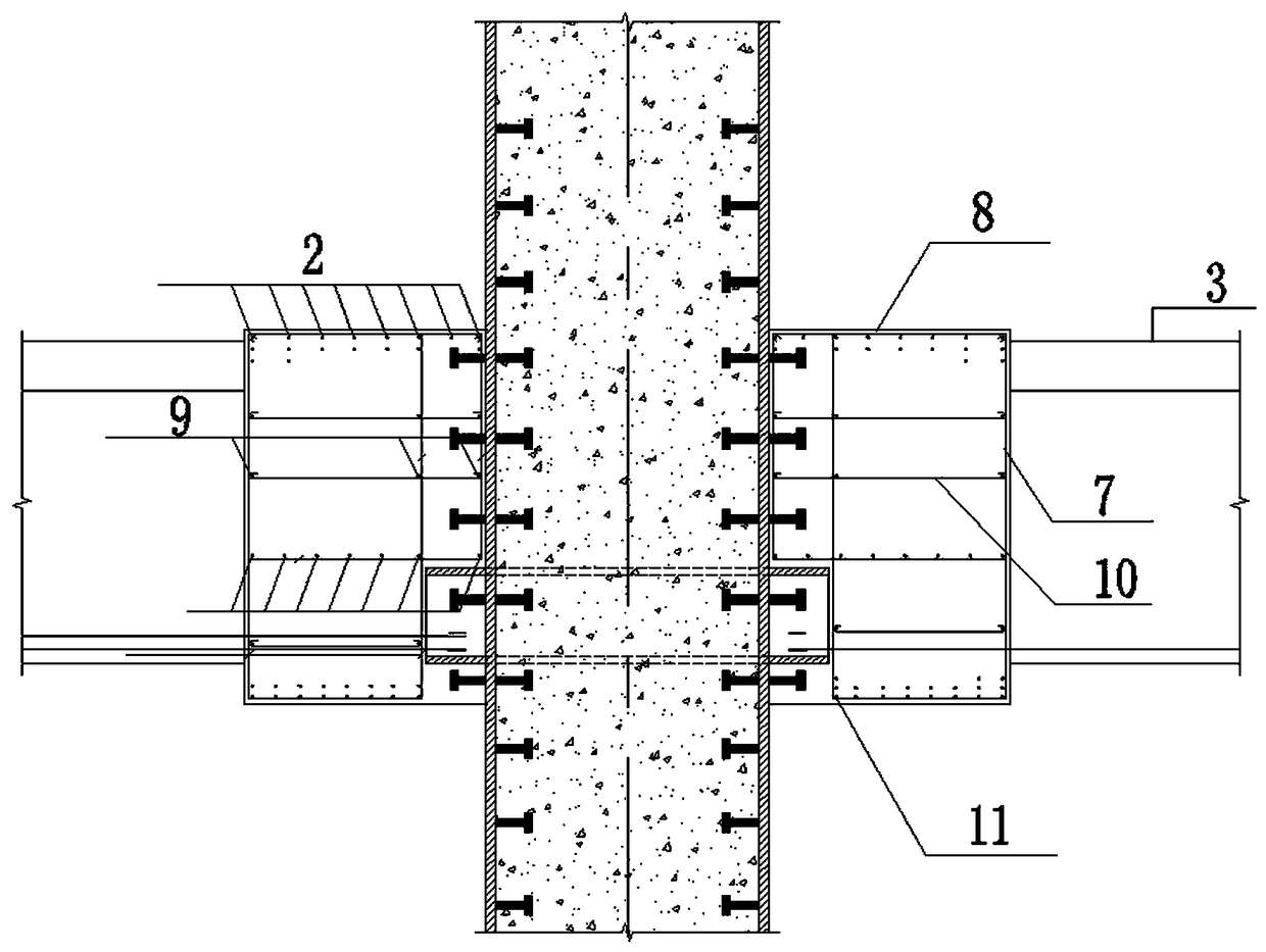
[0046] as attached Figure 1-Figure 13 As shown, the present invention provides a steel pipe concrete column ring beam node, including a steel pipe 5 for pouring concrete inside, a steel pipe concrete column 1 in the steel pipe 5, a stud 6 arranged on the steel pipe 5 and a steel pipe 5 installed on the outside Several ring beam main reinforcements 1, the ring beam main reinforcements 1 are installed on the outside of the steel pipe 5 th...


PUM


Abstract

The invention discloses a steel pipe concrete column ring beam joint and a steel bar binding construction method thereof. The steel pipe concrete column ring beam joint comprises a steel pipe, a studand ring beam main reinforcements, the ring beam main reinforcements are mounted on the outer side of the steel pipe, hoop reinforcements are fixedly bound on the ring beam main reinforcements and include first hoop reinforcements and second hoop reinforcements which are bound between the ring beam main reinforcements in a staggered manner, namely, the first hoop reinforcements and the second hoopreinforcements are bound on the peripheries of the ring beam main reinforcements, the second hoop reinforcements are arranged on two sides of each first hoop reinforcement, first hoop reinforcementsare arranged on two sides of each second hoop reinforcement, inner sides of the mounted first hoop reinforcements contact with the outer wall of the steel pipe, and the outer sides of the second hoopreinforcements and the first hoop reinforcements are bound on the outermost ring beam main reinforcement. According to the steel pipe concrete column ring beam joint and the steel bar binding construction method thereof, compared with the prior art, overall reinforcing steel bar binding processes are optimized, overall binding difficulty is reduced, and the joint is economical, durable, high in practicability and wide in application range and has excellent popularization and application values.

Description

technical field [0001] The invention relates to the construction field, in particular to a steel pipe concrete column ring beam node and a construction method for binding steel bars. Background technique [0002] With the continuous development of building structures, many steel and concrete composite structures have been applied to super high-rise buildings and special-shaped structures, among which steel pipe concrete columns are also being continuously applied in building structures. In steel and concrete composite structure buildings, for Strengthening the envelope structure can improve the overall seismic performance of the building structure. When steel pipe columns are connected to straight concrete beams, a reinforced concrete ring beam is designed based on the seismic theory of strong joints and weak members. Usually the design is copied from the design specification, and it is difficult to process and bind steel bars during on-site construction, which wastes manpow...

Claims


Application Information

Patent Timeline
Patent Type & Authority Applications(China)
IPC IPC(8): E04B1/58E04B1/30
CPCE04B1/185E04B1/30
Inventor 徐亮王彬肖闯苗壮张钦姚继鑫
Owner THE FIRST COMPARY OF CHINA EIGHTH ENG BUREAU LTD
Why Eureka
Try Eureka