Inert and damping integrated gas-filled damper

A shock absorber, an integrated technology, applied in the direction of liquid shock absorber, gas-hydraulic shock absorber, shock absorber, etc., can solve the problems of difficult processing and assembly, complex structure, and many components

Inactive Publication Date: 2015-07-08
JIANGSU UNIV
View PDF11 Cites 19 Cited by
  • Summary
  • Abstract
  • Description
  • Claims
  • Application Information

AI Technical Summary

Problems solved by technology

[0004] In view of the deficiencies in the prior art, the present invention provides an inertial and damping integrated gas shock absorber, which solves the problems of short life, complex structure, many components, difficult processing and assembly, high cost, and low production efficiency

Method used


Image

  • Inert and damping integrated gas-filled damper
  • Inert and damping integrated gas-filled damper
  • Inert and damping integrated gas-filled damper

Examples


Embodiment 1

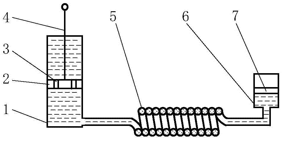
[0019] Such as figure 1 As shown, the inertial and damping integrated gas shock absorber includes a cylinder 1, a piston 2, a damping valve 3, a piston rod 4, a metal spiral tube 5, an external nitrogen tank 6, and a floating piston 7. The piston 2 is connected with the piston rod 4 and placed in the cylinder 1 , the cylinder 1 is divided into a rod chamber and a rodless chamber, and the damping valve 3 is arranged on the piston 2 . The floating piston 7 is placed in the external nitrogen tank 6, and the external nitrogen tank 6 is divided into upper and lower chambers, and the upper chamber of the external nitrogen tank 6 is filled with nitrogen. One end of the metal helical tube 5 communicates with the rodless cavity of the cylinder 1, and the other end communicates with the lower cavity of the external nitrogen tank 6, except for the lower cavity of the external nitrogen tank 6, the metal helical tube 5, and the lower cavity of the cylinder 1. Both the rod cavity and the r...

Embodiment 2

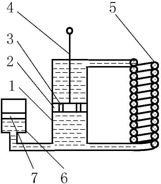
[0029] Such as figure 2 As shown, the difference from Embodiment 1 is that the metal helical tube 5 and the external nitrogen tank 6 are set at different positions. , The rodless chamber is connected; the lower chamber of the external nitrogen tank 6 is directly connected with the rodless chamber of the cylinder 1.

[0030] The specific implementation process of Embodiment 2 of the present invention will be further described below in conjunction with the accompanying drawings.

[0031] The cylinder 1, the piston 2, the piston rod 4 and the metal spiral tube 5 together constitute a fluid accumulator. However, the difference between the second embodiment and the first embodiment is that the inertia of the fluid inerter is different in the compression stroke and the stretch stroke, and the calculation method of the inertia of the compression stroke is the same as that of formula (1). Inertia of extension stroke, A in formula (1) 1 is the effective cross-sectional area after s...


PUM


Abstract

The invention provides an inert and damping integrated gas-filled damper. The inert and damping integrated gas-filled damper comprises a cylinder barrel, a piston, a damping valve, a piston rod, a metal spiral tube, an external nitrogen gas tank and a floating piston, wherein the piston and the piston rod are connected and are arranged in the cylinder barrel for dividing the cylinder barrel into a rod cavity and a rodless cavity, and a damping valve is arranged on the piston; at least one of the rod cavity and the rodless cavity is communicated with the metal spiral tube; the floating piston is arranged in the external nitrogen gas tank, and used for dividing the external nitrogen gas tank into upper and lower cavities; the external nitrogen gas tank and the metal spiral tube are connected in parallel or in series; one of upper and lower cavities of the external nitrogen gas tank is communicated with the metal spiral tube; the rod cavity and the rodless cavity of the cylinder barrel, the metal spiral tube, and one cavity, communicated with the metal spiral tube, of the external nitrogen gas tank is filled up with oil, and the other cavity of the external nitrogen gas tank is filled up with nitrogen gas. The inert and damping integrated gas-filled damper disclosed by the invention is simple in structure, relatively few in components, easy to process and assemble, relatively low in cost, high in production efficiency, and the service life of the searching damper is greatly prolonged.

Description

technical field [0001] The invention relates to a gas-filled shock absorber, in particular to a gas-filled shock absorber integrating inertial capacity and damping. Background technique [0002] The gas-filled shock absorber is a shock absorber that uses an air-sealing piston to divide the working cylinder into an oil chamber and an air chamber. Compared with the general double-tube shock absorber, it has the advantages of simple structure, low noise, better heat dissipation, good comfort, strong grip of the tire, and less strict requirements on the installation position. A class of shock absorbers disclosed in Chinese patents CN96108746.3, CN201110455149.5, CN201320453464.9 and CN201320536295.5 all belong to gas-filled shock absorbers and have the above advantages, but gas-filled shock absorbers are only one of the shock absorbers. It is a damping element and also an energy-consuming element, which can convert vibration energy into heat energy and dissipate it. Therefore,...

Claims


Application Information

Patent Timeline
Patent Type & Authority Applications(China)
IPC IPC(8): F16F9/10F16F9/32
CPCF16F9/06F16F9/344F16F7/1034F16F9/19F16F2230/20
Inventor 张孝良陈龙聂佳梅
Owner JIANGSU UNIV
Why Eureka
Try Eureka