
Drying device applied after washing of diodes

A dehydration device and cleaning technology, which are applied in the directions of drying gas arrangement, drying solid materials, drying machines, etc., can solve the problems of inability to spin the surface of the diode, time-consuming and labor-intensive, and inconvenient operation, so as to solve the problems of incomplete dehydration, Simple structure, practical and convenient effect

Inactive Publication Date: 2018-12-11
金寨崟鑫电子科技有限公司
View PDF12 Cites 3 Cited by
  • Summary
  • Abstract
  • Description
  • Claims
  • Application Information

AI Technical Summary

Problems solved by technology

[0004] Although the above-mentioned patent uses centrifugation to dry the diodes, this method cannot completely dry the residual liquid on the surface of the diodes. The pickling dies of the diodes need to be inserted into the installation grooves one by one, which is inconvenient to operate, time-consuming and labor-intensive. To solve the above problems, The invention introduces a dehydration device after diode cleaning

Method used


Image

  • Drying device applied after washing of diodes
  • Drying device applied after washing of diodes
  • Drying device applied after washing of diodes

Examples


Embodiment 1

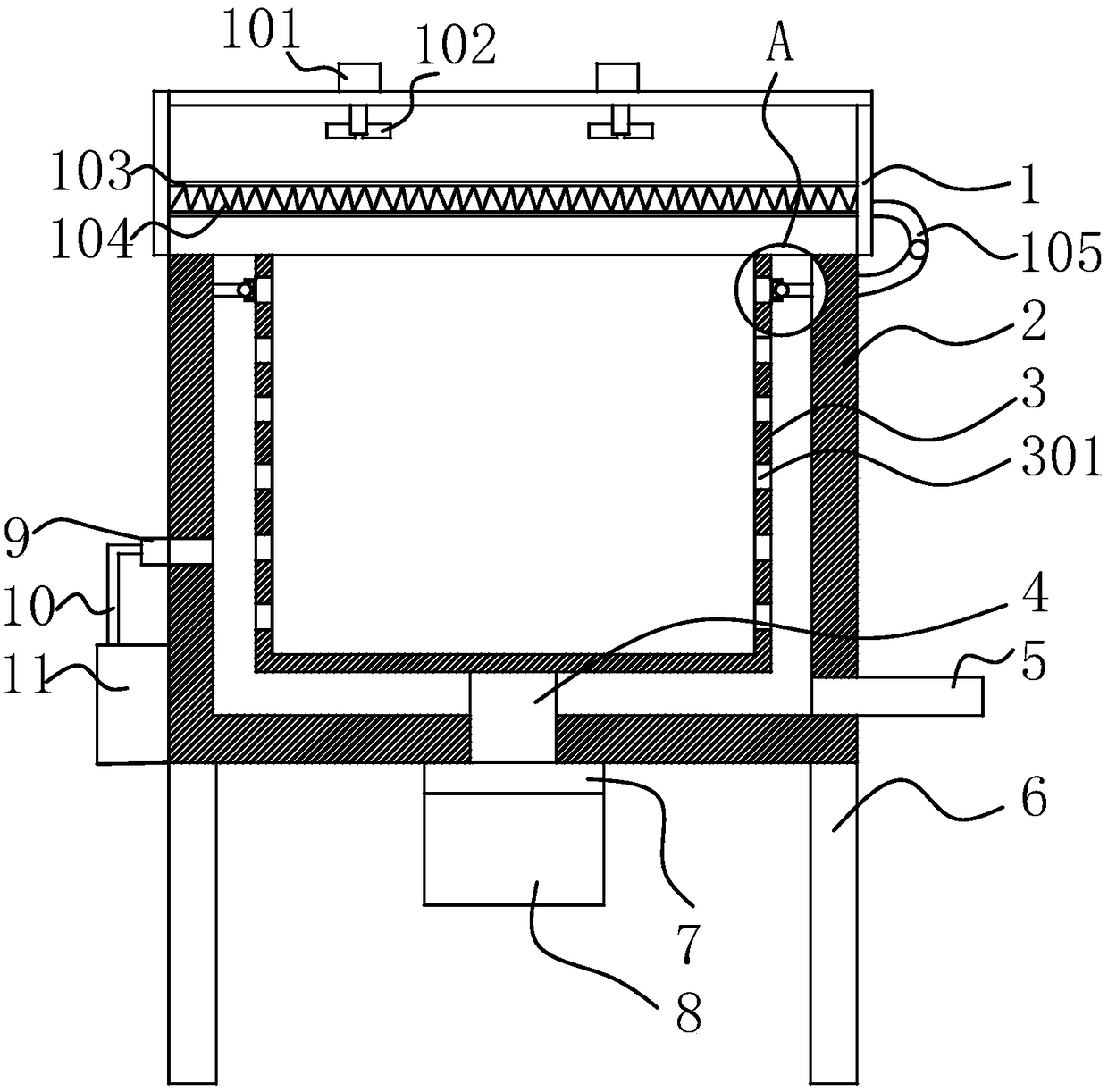
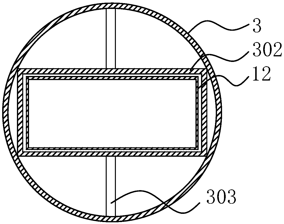
[0026] Such as figure 1 As shown, the present invention provides a dehydration device after diode cleaning, which includes a housing 2, a drum 3 disposed in the housing 2, and a cover 1 disposed on the housing 2, and is characterized in that the cover 1 passes through C A type hinge 105 is connected with the housing 2, the top of the cover 1 is provided with a first motor 101, the output end of the first motor 101 passes through the cover 1 and the end is provided with a fan blade 102, and the inner wall of the cover 1 is provided with a protective cover 103 , the protective cover 103 is provided with an electric heating wire 104, the surface of the rotating drum 3 is uniformly arranged with water leaks 301, the bottom of the rotating drum 3 is fixed with a rotating shaft 4, and the rotating shaft 4 is connected to the bottom of the housing 2 through a coupling 7. The second motor 8 is rotationally connected, one side of the housing 2 is provided with a water outlet 5, and the...

Embodiment 2

[0030] Such as figure 1 As shown, the present invention provides a dehydration device after diode cleaning, which includes a housing 2, a drum 3 disposed in the housing 2, and a cover 1 disposed on the housing 2, and is characterized in that the cover 1 passes through C A type hinge 105 is connected with the housing 2, the top of the cover 1 is provided with a first motor 101, the output end of the first motor 101 passes through the cover 1 and the end is provided with a fan blade 102, and the inner wall of the cover 1 is provided with a protective cover 103 , the protective cover 103 is provided with an electric heating wire 104, the surface of the rotating drum 3 is uniformly arranged with water leaks 301, the bottom of the rotating drum 3 is fixed with a rotating shaft 4, and the rotating shaft 4 is connected to the bottom of the housing 2 through a coupling 7. The second motor 8 is rotationally connected, one side of the housing 2 is provided with a water outlet 5, and the...


PUM


Abstract

The invention discloses a drying device applied after washing of diodes. The drying device comprises a casing, a rotary drum in the casing and a cover arranged on the casing. The cover is connected with the casing through a C-shaped hinge; first motors are arranged on the top of the cover; output ends of the first motors run through the cover and vanes are arranged at tails of the output ends of the first motors; a protective cover is arranged on the inner wall of the cover, and an electric heating wire is disposed inside the protective cover; a revolving shaft is fixedly arranged at the bottom of the rotary drum, and is in rotational connection with a second motor at the bottom of the casing through a coupling; a water outlet is arranged at one side of the casing, a gas inlet is formed inthe other side of the casing, and the gas inlet is communicated with a nitrogen cylinder through a pipeline. The drying device is simple in structure and convenient to use; with fittingly connectionof the cover, the casing, the rotary drum, a fixing drum and a holding frame, the problem of poor drying effect of existing diode drying devices is solved.

Description

Technical field: [0001] The invention relates to the field of diode production equipment, in particular to a dehydration device after diode cleaning. Background technique: [0002] Diode (English: Diode), among electronic components, a device with two electrodes that only allows current to flow in one direction, and many uses are for its rectification function. At present, light-emitting diodes are widely used in indicator lights of various electronic products, light sources for optical fiber communications, indicators and lighting of various instruments. In the process of producing diodes, the cleaning process must go through the production process when making components, especially electronic components such as diodes. In the previous part of the production process, it is inevitable that the diodes will be covered with a lot of dust. If the diodes are not Clean it. During use, the static electricity generated by dust will damage the diode or other tighter parts. After cle...

Claims


Application Information

Patent Timeline
Patent Type & Authority Applications(China)
IPC IPC(8): F26B5/08F26B21/00F26B25/16
CPCF26B5/08F26B21/001F26B21/004F26B25/16
Inventor 汪仁杰
Owner 金寨崟鑫电子科技有限公司
Learn More