A composite optical fiber communication system based on PROFIBUS bus

An optical fiber communication system and bus technology, applied in the direction of optical fiber transmission, transmission system, bus network, etc., can solve problems such as unstable communication signal transmission, and achieve the effects of easy troubleshooting, high reliability, and light burden

Inactive Publication Date: 2018-12-11
YUEYANG FOREST & PAPER CO LTD
View PDF7 Cites 0 Cited by
  • Summary
  • Abstract
  • Description
  • Claims
  • Application Information

AI Technical Summary

Problems solved by technology

[0003] The main purpose of the present invention is to provide a composite optical fiber communication system based on PROFIBUS bus, aiming to solve the problem of unstable communication signal transmission in the prior art

Method used


Image

  • A composite optical fiber communication system based on PROFIBUS bus
  • A composite optical fiber communication system based on PROFIBUS bus
  • A composite optical fiber communication system based on PROFIBUS bus

Examples


no. 1 example

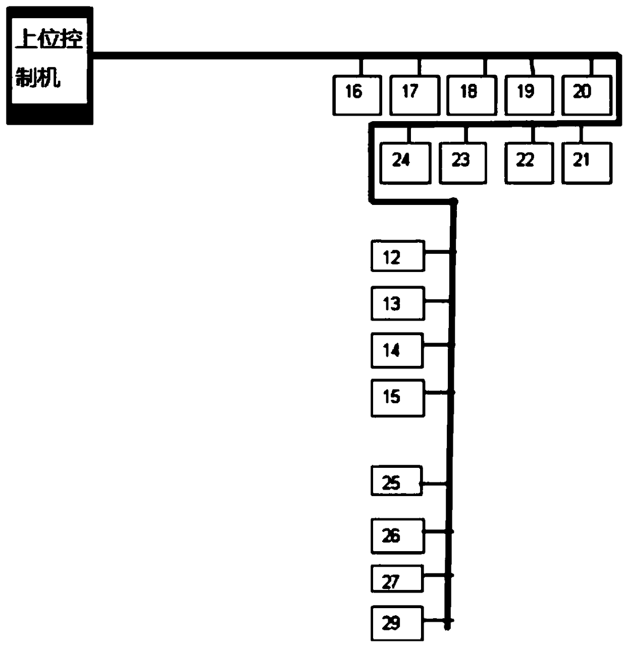
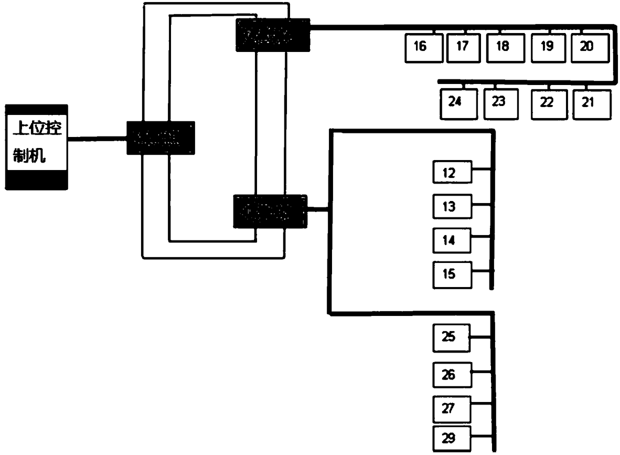
[0036] Please refer to Figure 3 to Figure 4 , in the first embodiment of the present invention, the composite optical fiber communication system based on the PROFIBUS bus includes: a host controller, a photoelectric conversion module and a plurality of transmission control points; wherein the photoelectric conversion module includes at least three photoelectric conversion modules, They are: the first photoelectric conversion module OLM-01, the second photoelectric conversion module OLM-02, and the third photoelectric conversion module OLM-03. The signal input terminal of the first photoelectric conversion module OLM-01 is connected to the host controller, and the signal output terminal of the first photoelectric conversion module OLM-01 is used to connect the signal input terminal of the second photoelectric conversion module OLM-02 and the third photoelectric conversion module respectively. The signal input terminal of the module OLM-03, the signal output terminal of the sec...

no. 2 example

[0044] Based on the previous embodiment, the PROFIBUS-based composite optical fiber communication system provided by the second embodiment of the present application includes: a host controller, a photoelectric conversion module and a plurality of transmission control points; wherein the photoelectric conversion module includes: the first The photoelectric conversion module OLM-01, the second photoelectric conversion module OLM-02, the third photoelectric conversion module OLM-03 and the fourth photoelectric conversion module OLM-04. The signal input end of the first photoelectric conversion module OLM-01 is connected to the host controller, and the signal output end of the first photoelectric conversion module OLM-01 is respectively connected to the signal input end of the second photoelectric conversion module OLM-02, the third photoelectric conversion module OLM The signal input terminal of -03 and the signal input terminal of the fourth photoelectric conversion module OLM-0...


PUM


Abstract

The invention discloses a composite optical fiber communication system based on PROFIBUS bus, which comprises an upper control computer, a photoelectric conversion module and a plurality of transmission control points. Wherein the photoelectric conversion module comprises a first photoelectric conversion module, a second photoelectric conversion module and a third photoelectric conversion module.The signal input terminal of the first photoelectric conversion module is connected with an upper controller, the signal output terminal of the first photoelectric conversion module is respectively connected with the signal input terminal of the second photoelectric conversion module and the signal input terminal of the third photoelectric conversion module, the signal output terminal of the second photoelectric conversion module is connected to one group of the plurality of transmission control points, the signal output terminal of the third photoelectric conversion module is connected to theother group of the plurality of transmission control points, and the signal output terminal of the second photoelectric conversion module is connected to the signal output terminal of the third photoelectric conversion module. The technical scheme of the invention enhances the communication signal, improves the anti-interference ability of the network, effectively reduces the communication burdenof the PROFIBUS network, and improves the stability of the communication system.

Description

technical field [0001] The invention relates to the technical field of electric control, in particular to a composite optical fiber communication system based on a PROFIBUS bus. Background technique [0002] PROFIBUS is an international, open, independent of equipment manufacturers Fieldbus standard. PROFIBUS transmission speed It can be selected within the range of 9.6kbaud~12Mbaud and when the bus system starts, all devices connected to the bus should be set to the same speed. Widely applicable to Manufacturing Automation , process industry automation and building , transportation, power and other fields of automation. Since its birth, PROFIBUS has occupied more than 80% of the communication control share in the field bus technology field. However, the existing PROFIBUS bus architecture such as figure 1 As shown, the upper control machine and each transmission control point ( figure 1 Among them are their corresponding numbers) between them, the bus-type topol...

Claims


Application Information

Patent Timeline
IPC IPC(8): H04B10/278H04B10/25H04L12/40
CPCH04B10/25H04B10/278H04L12/40006H04L2012/40221
Inventor 李尧森黄玉合
Owner YUEYANG FOREST & PAPER CO LTD
Why Eureka
Try Eureka