Jamming device and jamming method

A technology of jamming equipment and jamming trigger, applied in the field of jamming

Pending Publication Date: 2018-12-11
ROHDE & SCHWARZ GMBH & CO KG
View PDF5 Cites 10 Cited by
  • Summary
  • Abstract
  • Description
  • Claims
  • Application Information

AI Technical Summary

Problems solved by technology

However this also blocks the band for any other use

Method used


Image

  • Jamming device and jamming method
  • Jamming device and jamming method
  • Jamming device and jamming method

Examples


Embodiment Construction

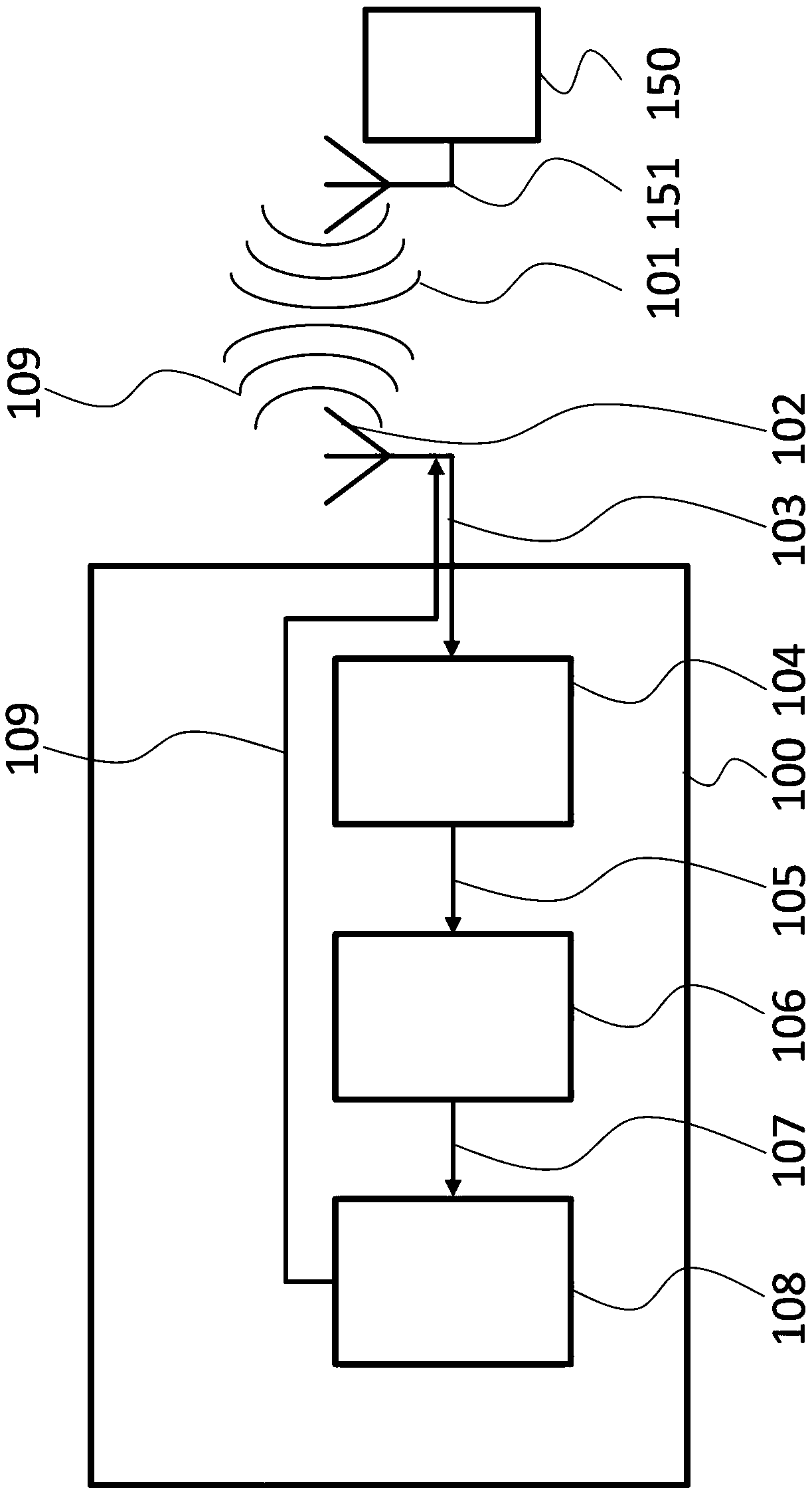
[0075] figure 1 A block diagram of an embodiment of a jamming device 100 for jamming a frequency hopping signal 101 transmitted by a transmitter 150 via an antenna 151 is shown. The transmitter 150 may be, for example, for remote control of, for example, a drone.

[0076] Interfering device 100 includes a receive antenna 102 electrically coupled to a transmission detection unit 104 . The emission detection unit 104 is coupled to a signal analysis unit 106 which is coupled to a signal interference unit 108 .

[0077] The receive antenna 102 receives the signal 103 and provides the received signal 103 to the emission detection unit 104 . The emission detection unit 104 detects in the received signal 103 an emission 105 which may be related to the frequency hopping signal 101 . Emission 105 may be, for example, a high energy emission in the relevant frequency spectrum. "High energy" relates to emitted energy detectable over background noise.

[0078] The emission detection u...


PUM


Abstract

The present invention provides a jamming device for jamming a frequency hopping signal, the jamming device comprising at least one receiving antenna configured to receive signals in the signal spectrum of the frequency hopping signal, an emission detection unit configured to detect relevant emissions in the received signals that pertain to the frequency hopping signal, and an effectivity analysisunit configured to determine and output the effectivity of the emission detection unit based on the number of detected relevant emissions and an expected number of relevant emissions of the frequencyhopping signal. Further, the present invention provides a respective jamming method.

Description

technical field [0001] The invention relates to jamming devices for jamming frequency hopping signals. The invention also relates to a corresponding interference method. Background technique [0002] While theoretically applicable to any system used to jam wireless signals, the invention and its potential problems will hereinafter be described in connection with an FHSS jammer. [0003] In a Frequency Hopping Spread Spectrum or FHSS system, radio signals are transmitted by rapidly switching carriers among many frequency channels. Frequency channel switching is usually based on a pseudo-random sequence known to both the transmitter and receiver. FHSS systems thus spread their signals across rapidly changing frequencies. The available frequency band may eg be divided into sub-frequencies. The transmitted signal then rapidly transitions or hops among these sub-frequencies in a predetermined sequence. [0004] FHSS signals are used eg in first generation WLAN systems, in Bl...

Claims


Application Information

Patent Timeline
Patent Type & Authority Applications(China)
IPC IPC(8): H04K3/00H04B1/715
CPCH04B1/715H04K3/45H04K3/62H04K3/42H04K3/92
Inventor 延斯·屈内托马斯·施密德
Owner ROHDE & SCHWARZ GMBH & CO KG
Why Eureka
Try Eureka