Rotary locking type safety insulin injection needle
An insulin injection and locking technology, applied in the directions of needles, hypodermic injection devices, and devices introduced into the body, etc., can solve the problems of inability to carry out back-end protection, low stability and reliability, and inability to ensure stable and reliable work. Achieve the effect of highlighting substantive features, reasonable design plans, and significant technological progress
- Summary
- Abstract
- Description
- Claims
- Application Information
AI Technical Summary
Problems solved by technology
Method used
Image
Examples
Embodiment 1
[0063] Example 1: A rotation-locking safety insulin injection needle (with front needle tip protection and rear needle tip protection)
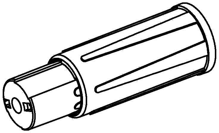
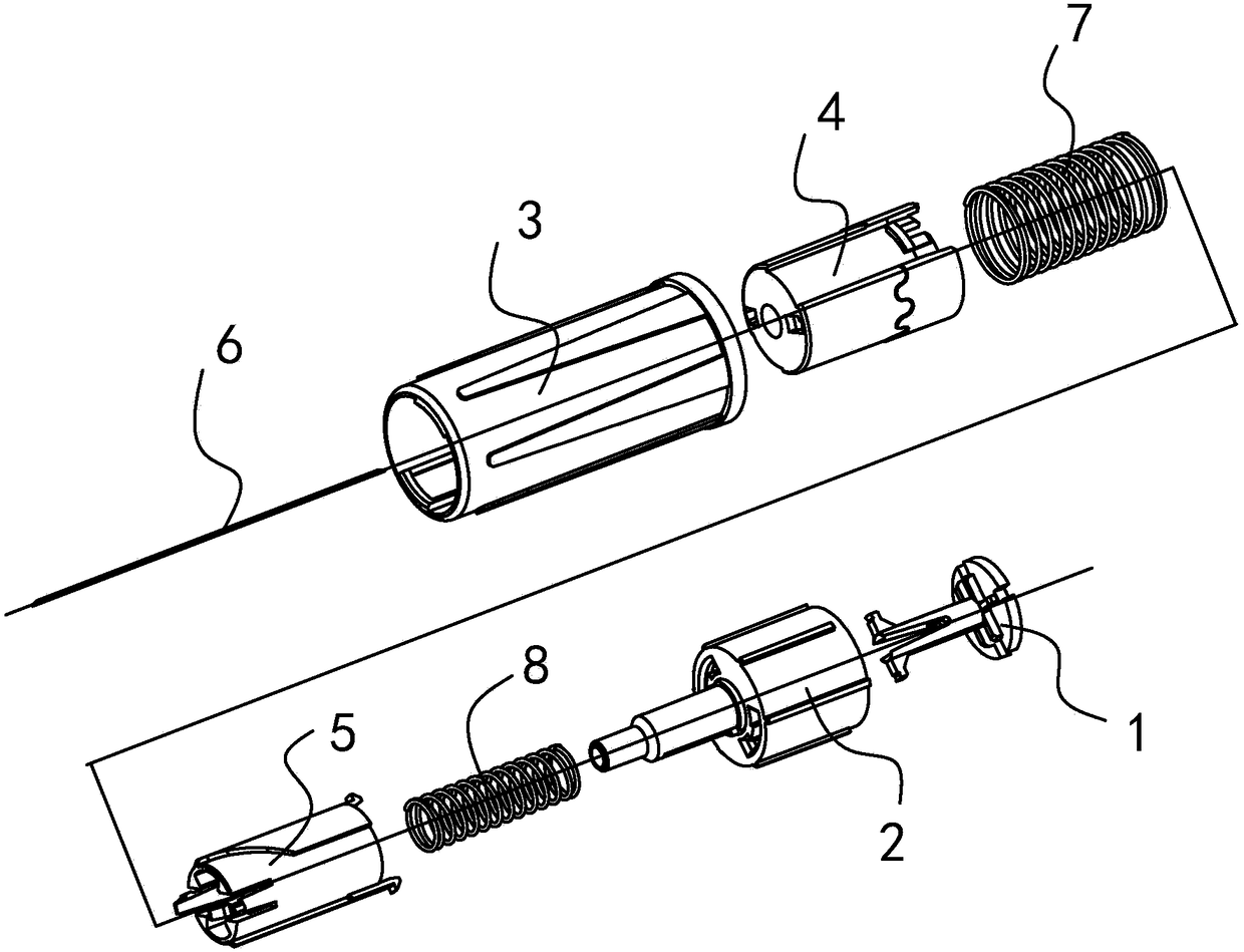
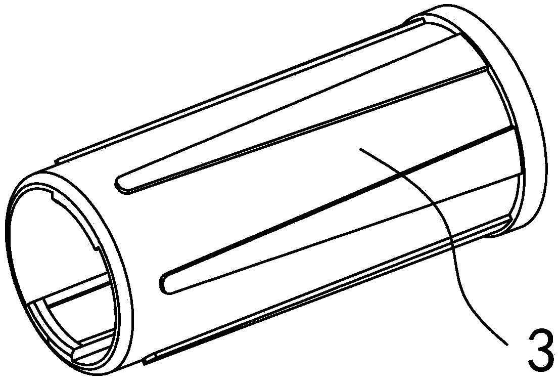
[0064] Such as Figure 1-14 As shown, the insulin injection needle includes a needle body 6, a middle sleeve 3, a front sleeve 4, a front spring 7, a rotating tube 5, a rear spring 8, a threaded sleeve 2 and a tail cap 1 (see figure 2 ). As a complete product, the insulin injection needle is usually provided with a jacket (also known as a "big sheath"), which is a sleeve structure and is usually placed outside the middle sleeve 3 to protect the insulin injection needle as a whole. In this implementation, since the jacket has nothing to do with the innovation of the present invention, it will be omitted in the following text description and accompanying drawings.
[0065] The structure of each part of the insulin injection needle of this embodiment is described in turn below:
[0066] 1. needle body 6
[0067] The needle body 6 is a tube...
Embodiment 2
[0099] Example 2: A rotation-locking safety insulin injection needle (with front needle tip protection but without rear needle tip protection)
[0100] The insulin injection needle includes a needle body 6 , a middle sleeve 3 , a front sleeve 4 , a front spring 7 , a rotating tube 5 and a threaded sleeve 2 .
[0101] The difference between embodiment 2 and embodiment 1 is that: the tail cap 1 and the rear spring 8 are eliminated, and only the front needle point protection structure is provided, and the rear needle point protection structure is not provided. Others are basically the same as in Embodiment 1, and will not be described again here.
[0102] Relevant content and change description in the above embodiment are as follows:
[0103] 1. In the above two embodiments, the slope track 51 is formed by a guide surface on the outer edge of the rotating tube 5, and the slope action part 45 corresponding to the guide surface is a convex part, and the convex part slides and con...
PUM
 Abstract
Description
Claims
Application Information
 - R&D
- Intellectual Property
- Life Sciences
- Materials
- Tech Scout
- Unparalleled Data Quality
- Higher Quality Content
- 60% Fewer Hallucinations
Browse by: Latest US Patents, China's latest patents, Technical Efficacy Thesaurus, Application Domain, Technology Topic, Popular Technical Reports.
© 2025 PatSnap. All rights reserved.Legal|Privacy policy|Modern Slavery Act Transparency Statement|Sitemap|About US| Contact US: help@patsnap.com


