Supercharge Your Innovation With Domain-Expert AI Agents!

Defibrillator bridge discharge circuit capable of precisely controlling conduction process

A discharge circuit and precise control technology, applied in the field of medical equipment, can solve problems such as endangering the life safety of patients, difficult design of defibrillator hardware circuit, damage to internal components of defibrillator, etc., to ensure safety and reliability, and optimize control Methods and effects of solving potential safety hazards

Inactive Publication Date: 2018-12-14
SHAANXI QINMING MEDICAL CO LTD +1
View PDF3 Cites 3 Cited by
  • Summary
  • Abstract
  • Description
  • Claims
  • Application Information

AI Technical Summary

Problems solved by technology

[0003] In order to ensure the success of defibrillation, it is usually necessary to release high voltage and high current on the target load, but if the discharge bridge circuit is not properly controlled, it may damage the internal components of the defibrillator, and even endanger the life of the patient, so the safety of the defibrillation discharge circuit Performance and reliability are very important, which requires precise control of the discharge process of the discharge bridge, and the response speed must be fast enough
[0004] In addition, since the discharge action of the discharge bridge is controlled by the main control module working under low voltage conditions, the control of the electronic switch at the high voltage end of the discharge bridge is a difficult point in the design of the defibrillator hardware circuit

Method used


Image

  • Defibrillator bridge discharge circuit capable of precisely controlling conduction process
  • Defibrillator bridge discharge circuit capable of precisely controlling conduction process
  • Defibrillator bridge discharge circuit capable of precisely controlling conduction process

Examples


Embodiment Construction

[0023] The present invention will be further described in detail below in conjunction with the accompanying drawings and specific embodiments.

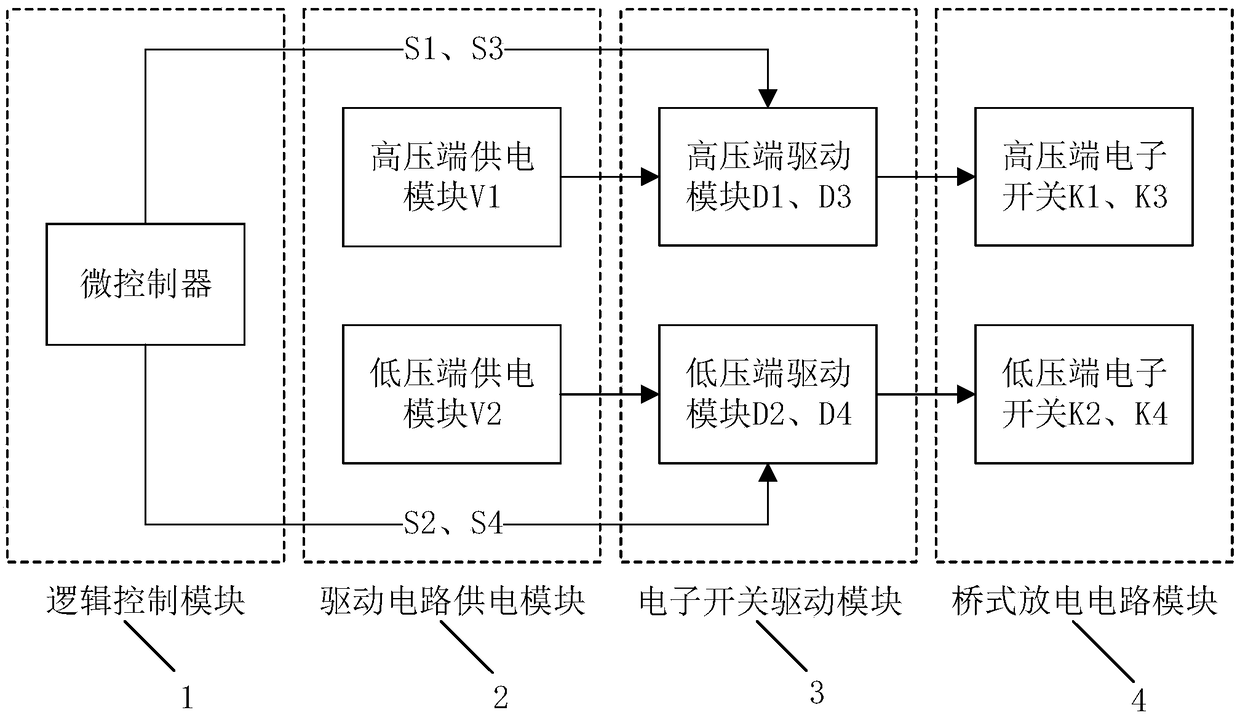
[0024] see figure 1 The defibrillator bridge discharge circuit capable of precisely controlling the conduction process of the present invention includes a logic control module 1 , a drive circuit power supply module 2 , an electronic switch drive module 3 and a bridge discharge circuit module 4 .

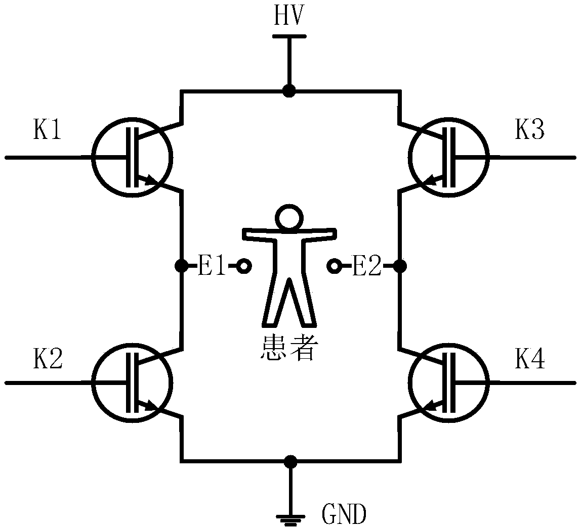
[0025] In this embodiment, the bridge discharge circuit module 4 includes two electronic switches K1 and K3 at the high-voltage end and two electronic switches K2 and K4 at the low-voltage end, and the four electronic switches all use IGBTs. IGBT is an insulated gate bipolar transistor (Insulated Gate Bipolar Transistor), which is a voltage-controlled electronic device composed of a bipolar transistor (BJT) and a metal oxide semiconductor field effect transistor (MOSFET). It also has the characteristics of low MOSFET driving power and fast...


PUM


Abstract

The invention provides a defibrillator bridge discharge circuit capable of precisely controlling the conduction process. The defibrillator bridge discharge circuit comprises a logic control module, adriving circuit power supply module, an electronic switch driving module and a bridge discharge circuit module. The bridge discharge circuit module realizes the emission control of the two-phase exponential truncated waves through orderly conduction of the electronic switch. The driving circuit power supply module is used for supplying power to the electronic switch driving module. The electronicswitch driving module provides sufficient voltage and current for conduction of the electronic switch in the bridge discharge circuit module. The logic control module outputs a control signal to control on-off of the electronic switch driving module so as to realize control of the conduction order and time of the electronic switch. The safety hidden trouble existing in the control process of the discharge circuit can be solved, the control method of the electronic switch at the high voltage end of the discharge bridge can be optimized, and the accurate controllable two-phase exponential truncated wave emission on the target load can be realized.

Description

technical field [0001] The invention belongs to the field of medical equipment, and in particular relates to a defibrillator bridge discharge circuit which can precisely control the conduction process. Background technique [0002] Sudden cardiac death is a natural death caused by cardiac causes. Ventricular fibrillation is the main cause of sudden cardiac death. Clinically, electric shock defibrillation is often used to terminate ventricular fibrillation. Studies have shown that using biphasic exponential truncated waves for electrical defibrillation can effectively reduce the defibrillation threshold and improve the success rate of defibrillation. The general method to realize biphasic exponential truncated wave delivery in a defibrillator is: store electric energy in a capacitor, and then control the orderly conduction of the discharge bridge to complete the discharge on the target load (usually the patient). [0003] In order to ensure the success of defibrillation, it ...

Claims


Application Information

Patent Timeline
Patent Type & Authority Applications(China)
IPC IPC(8): A61N1/39
CPCA61N1/39
Inventor 黄彦淇邬小玫王建飞金华
Owner SHAANXI QINMING MEDICAL CO LTD
Features
  • R&D
  • Intellectual Property
  • Life Sciences
  • Materials
  • Tech Scout
  • Unparalleled Data Quality
  • Higher Quality Content
  • 60% Fewer Hallucinations
Learn More