Microfluidic chip and microfluidic system

A microfluidic chip and microfluidic technology, applied in the field of microfluidics, can solve problems such as disadvantages

Active Publication Date: 2018-12-14
BOE TECH GRP CO LTD
View PDF6 Cites 10 Cited by
  • Summary
  • Abstract
  • Description
  • Claims
  • Application Information

AI Technical Summary

Problems solved by technology

However, with the improvement of detection requirements in the field of biomedicine, the technical solution of using the above-mentioned microfluidic detection system to measure droplets in the microfluidic chip has been slightly disadvantaged.

Method used


Image

  • Microfluidic chip and microfluidic system
  • Microfluidic chip and microfluidic system
  • Microfluidic chip and microfluidic system

Examples


Embodiment Construction

[0032] Reference will now be made in detail to the exemplary embodiments, examples of which are illustrated in the accompanying drawings. When the following description refers to the accompanying drawings, the same numerals in different drawings refer to the same or similar elements unless otherwise indicated. The implementations described in the following exemplary examples do not represent all implementations consistent with the present invention. Rather, they are merely examples of apparatuses and methods consistent with aspects of the invention as recited in the appended claims.

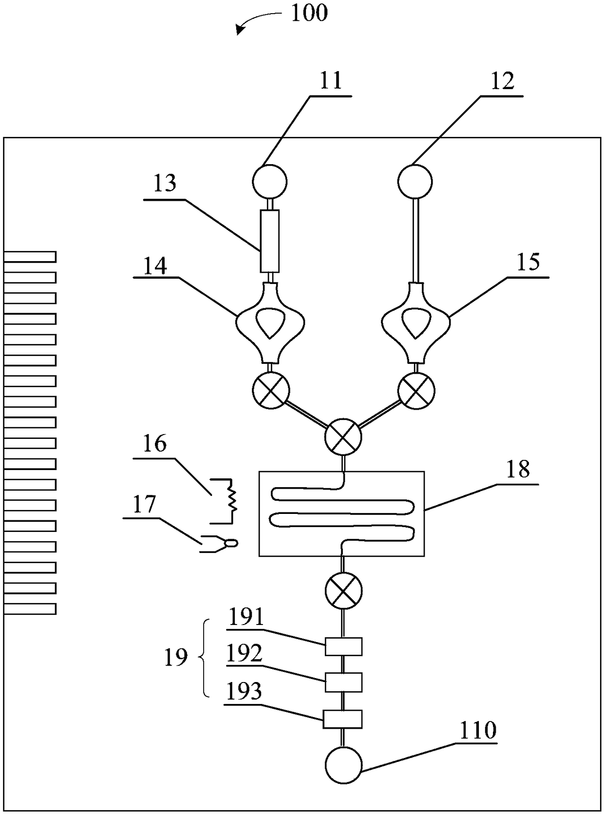
[0033] Such as figure 1 As shown, in the related art, the microfluidic chip 100 can generally include a sample inlet 11, a reagent inlet 12, a DEP (Dielectrophoresis, dielectrophoresis) filter 13, a pump 14, 15, a heater 16, a resistance temperature detector (Resistance Temperature Detector (referred to as RTD) 17, polymerase chain reaction chamber (PCR Chamber) 18, electrode 19 and outlet 110,...


PUM


Abstract

The invention relates to a microfluidic chip and a microfluidic system. The microfluidic chip comprises a droplet flow channel, at least two grating regions, a light source and a wavelength detector,wherein grating constants of the at least two grating regions are different and the grating regions are arranged in the length direction of the droplet flow channel; when droplets are absent in the droplet flow channel, the at least two grating regions reflect light with different designated wavelengths, and when the droplets are present in the droplet flow channel, wavelength of light reflected by the grating regions opposite to the positions of the droplets is different from the designated wavelength; the light source is located at the first end of the droplet flow channel in the length direction and is used for providing incident light including the different designated wavelengths; the wavelength detector detects reflected light after the incident light passes through the grating regions when at the first end, and detects transmitted light after the incident light passes through the grating regions when at the second end opposite to the first end. According to the embodiment, detection accuracy of the droplets in the microfluidic chip can be improved, and accurate control of the droplets can be realized.

Description

technical field [0001] The invention relates to the field of microfluidic technology, in particular to a microfluidic chip and a microfluidic system. Background technique [0002] In related technologies, a microfluidic system generally includes a microfluidic chip for realizing specific functions, a microfluidic operation control device, and a control and detection device for signal acquisition. Wherein, the microfluidic operation control device is located outside the microfluidic chip, and may include a microfluidic detection system for detecting liquid parameters, and the liquid parameters may include position, shape, flow velocity, contact angle, and the like. However, with the improvement of detection requirements in the field of biomedicine, the technical solution of using the above-mentioned microfluidic detection system to measure the droplets in the microfluidic chip has been slightly disadvantaged. Contents of the invention [0003] The invention provides a micr...

Claims


Application Information

Patent Timeline
Patent Type & Authority Applications(China)
IPC IPC(8): B01L3/00
CPCB01L3/5027G01N21/41G01P13/0086G01N15/1484G01N21/255G01N21/31
Inventor 谭纪风孟宪芹王维孟宪东陈小川
Owner BOE TECH GRP CO LTD
Why Eureka
Try Eureka