Printed circuit board type discharge electrode

A technology of discharge electrodes and printed circuit boards, which is applied in the field of discharge electrodes for high voltage discharge, can solve the problems of inconvenient installation, easy bending and breakage of electrodes, and achieve the effects of easy installation and fixation, good vibration resistance and cost reduction.

Pending Publication Date: 2018-12-14
718TH RES INST OF CHINA SHIPBUILDING INDAL CORP
View PDF14 Cites 1 Cited by
  • Summary
  • Abstract
  • Description
  • Claims
  • Application Information

AI Technical Summary

Problems solved by technology

[0003] In view of this, the present invention provides a printed wire plate type discharge electrode, which can solve the problems of inconvenient installation of the existing high-voltage discharge wire electrode, and the problems of easy bending, breakage and oxidation during mobile use

Method used


Image

  • Printed circuit board type discharge electrode
  • Printed circuit board type discharge electrode
  • Printed circuit board type discharge electrode

Examples


Embodiment 1

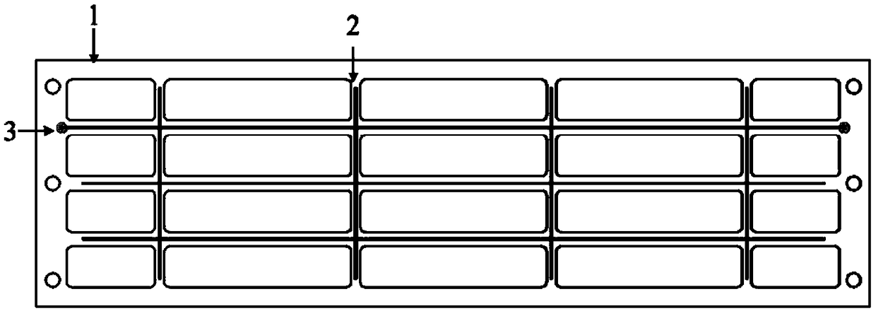
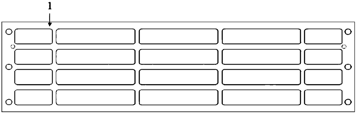
[0026] This embodiment provides a printed wire plate type discharge electrode, see attached figure 1 and 2 , including: substrate 1, wire electrodes 2 and solder joints 3;

[0027] The substrate 1 is a hollow plate made of insulating material to facilitate the passage of airflow, and the thickness of the substrate 1 is not less than 0.5mm; in this embodiment, the substrate 1 is a rectangular plate, and the rectangular plate is processed with rectangular Hollow hole, the rectangular hollow hole separates the rectangular plate into an outer frame and criss-crossing horizontal support beams and longitudinal support beams in the outer frame; the outer frame is used for fixing and installing the substrate 1, and no wire electrodes are printed on it 2. The horizontal support beams and vertical support beams are used to carry the discharge electrodes, on which the wire electrodes 2 are printed, and the distance between adjacent horizontal support beams or adjacent vertical support b...

Embodiment 2

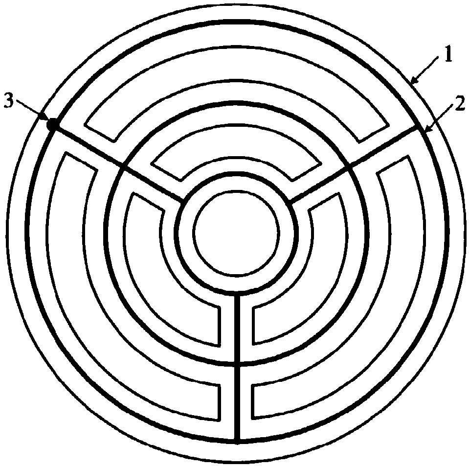
[0033] This embodiment provides a printed wire plate type discharge electrode, see attached image 3 , except that the layout of the substrate 1 shape and the wire electrode 2 is different from that of Embodiment 1, all the others are the same;

[0034] The base plate 1 in this embodiment is a circular plate, and the circular plate is processed with two circles of circularly distributed arc-shaped hollow holes and a central circular hole. The arc-shaped hollow holes and the central circular hole separate the circular plate into Three rings of the shaft and three radial support beams connecting the three rings; the wire electrode 2 is printed on the rings and the radial support beams of the substrate 1 by printing or deposition process.


PUM


Abstract

The invention discloses a printed circuit board type discharge electrode, and belongs to the technical field of discharge electrodes for high-voltage discharge. The printed circuit board type discharge electrode comprises a substrate, wire electrodes and welding points. The substrate is made of an insulation material. Four or more hollowed holes are machined in the substrate, and the substrate isdivided by the hollowed holes into supporting beams distributed in a cross manner. One corresponding wire electrode is printed on each supporting beam of the substrate through a printing or depositionprocess, and the surface of each supporting beam is coated with insulation paint to cover the corresponding wire electrode. The two wire electrodes at each intersection are connected, and therefore acommunicating wire electrode net is formed by all the wire electrodes. The one or more welding points are arranged on the edge of the substrate, and the welding points communicate with the wire electrodes. After the wire electrodes are electrically with an outer high-voltage power source through one welding point, the printed circuit board type discharge electrode carries out discharge work. According to the printed circuit board type discharge electrode, the problems that existing wire electrodes for high-voltage discharge are inconvenient to mount, and the wire electrodes are prone to beingbent, broken and oxidized during moving and using can be solved.

Description

technical field [0001] The invention belongs to the technical field of discharge electrodes for high-voltage discharge, and in particular relates to a printed wire plate type discharge electrode. Background technique [0002] As the discharge electrode for high-voltage discharge, there are plate type, needle type and wire type. In recent years, wire electrodes have been widely used in air purification devices. Commonly used wire electrodes are tungsten wires and molybdenum wires with small curvature. In the application, the selected metal wires are stretched and fixed on the insulating support, which is inconvenient to operate; and because the wire electrodes are suspended on the support, they are easy to bend during transportation and assembly. Deformation, breakage, and easy oxidation under medium and high pressure conditions. Therefore, it is necessary to provide a novel high-voltage discharge electrode to solve the above problems. Contents of the invention [0003] ...

Claims


Application Information

Patent Timeline
Patent Type & Authority Applications(China)
IPC IPC(8): B03C3/41
CPCB03C3/41
Inventor 孙少凡高崧孙任辉张平艾长波
Owner 718TH RES INST OF CHINA SHIPBUILDING INDAL CORP
Why Eureka
Try Eureka