Component hydroforming springback accurate compensation method based on liquid volume control

A liquid volume, hydroforming technology, applied in the field of accurate springback compensation of metal plate components, can solve the problem of inability to solve different batches, the accuracy of the part profile cannot be accurately controlled, and the performance changes of the plate cannot be compensated online and in-situ for springback, etc. problems, to achieve the effect of shortening the mold debugging cycle, shortening the debugging cycle and improving the forming accuracy

Active Publication Date: 2018-12-14
HARBIN INST OF TECH
View PDF5 Cites 8 Cited by
  • Summary
  • Abstract
  • Description
  • Claims
  • Application Information

AI Technical Summary

Problems solved by technology

[0005] The purpose of the present invention is to solve the problem that the existing hydroforming uses pressure to control springback, which cannot solve the problems of different batches of sheet material performance changes and in-situ compensation for springback; The surface accuracy cannot be accurately controlled, and the springback can be quickly and accurately compensated without modifying the mold

Method used


Image

  • Component hydroforming springback accurate compensation method based on liquid volume control
  • Component hydroforming springback accurate compensation method based on liquid volume control
  • Component hydroforming springback accurate compensation method based on liquid volume control

Examples


specific Embodiment approach 1

[0053] Specific implementation mode one: this implementation mode is realized through the following steps:

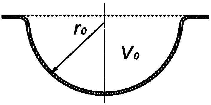
[0054] Step 1: Calculate the theoretical volume V of the corresponding surface according to the design surface of the curved panel 0 ;

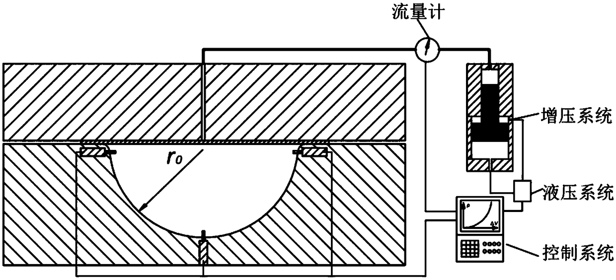
[0055] Step 2: Put the slab into the mold and close the mold, fill the mold with liquid water and pressurize it through an external pressurization system, so that the slab starts to be formed by liquid punch under the action of liquid pressure;

[0056] Step 3: Use a flowmeter to record the change of the liquid flow rate filled into the mold. When the volume of liquid filled into the mold reaches V 0 When the liquid filling and unloading are stopped through the control system;

[0057] Step 4: Use the displacement sensor to measure the distance between the unloaded part surface and the corresponding mold surface on-line, calculate the measured volume V of the unloaded part, and calculate V 0 The volume difference with V is △V;

[0...

specific Embodiment approach 2

[0060] Considering the overall process of ultra-high pressure, in order to avoid the error caused by the volume compression of the liquid under ultra-high pressure and affect the precise control of the liquid volume, on the basis of steps 1 to 5 of the specific embodiment 1, this embodiment also includes the following steps :

[0061] Step 6: According to the liquid volume compression △V p Relational formula △V with liquid pressure p p =β·p·V, calculate the volume of liquid filled into the mold as (V 0 +△V) when the liquid volume compression △V p =β·p·(V 0 +△V), where β is the compressibility coefficient of the liquid medium;

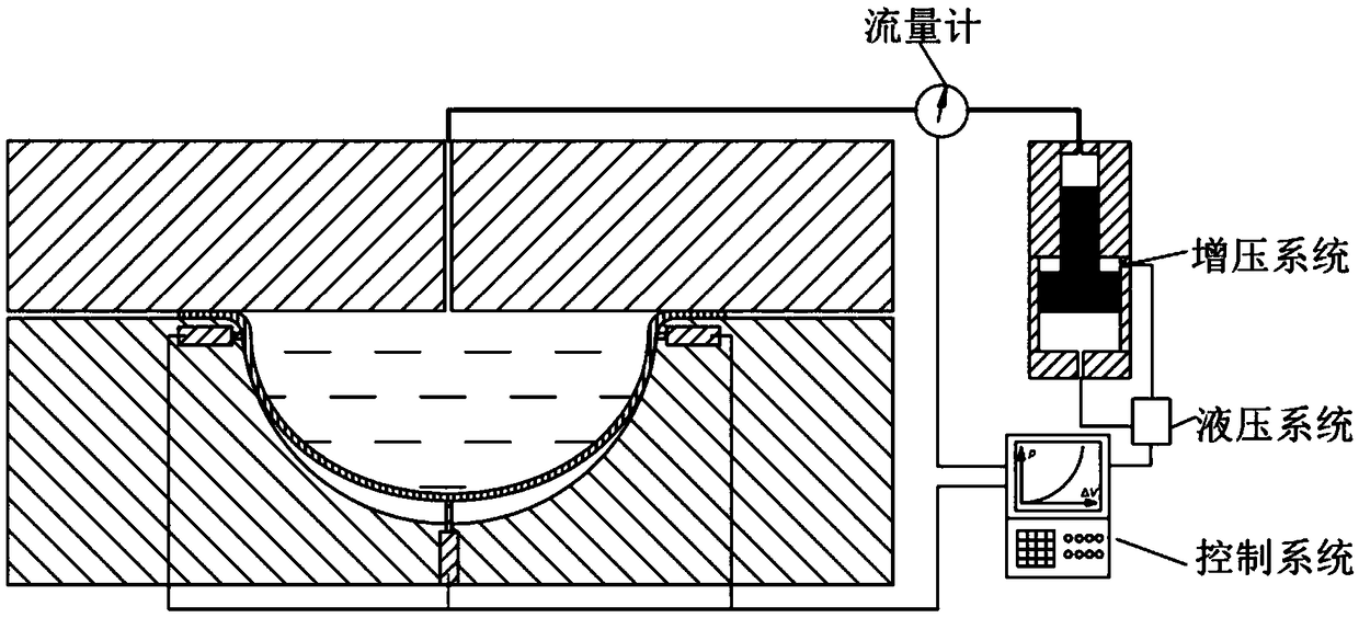
[0062] Step 7: Fill the mold with water and pressurize again to cause the mold to deform elastically. Use a flowmeter to record the change of the amount of water filled into the mold. When the volume of liquid filled into the mold reaches V 0 +△V+△V p When the liquid is filled, stop the liquid filling through the control system, and take out the c...

specific Embodiment approach 3

[0064] Considering that there are errors in mold surface processing, when the actual size of the mold cavity is smaller than the lower tolerance of the part size, the invention does not need to modify the mold to realize high-precision forming of curved plate components at one time. This implementation mode includes the following steps:

[0065] Step 1: Calculate the corresponding theoretical volume V according to the design surface of the curved panel and the measured surface of the mold cavity 0 and mold cavity volume V 1 , calculate V 0 with V 1 The volume difference ΔV 1 =V 0 -V 1 ;

[0066] Step 2: Put the slab into the mold and close the mold, fill the mold with water and pressurize it through an external pressurization system, so that the slab starts to be formed by liquid punch under the action of water pressure;

[0067] Step 3: Use a flowmeter to record the change in the amount of water filled into the mold. When the volume of liquid filled into the mold reach...


PUM


Abstract

The invention discloses a component hydroforming springback accurate compensation method based on liquid volume control, and relates to a metal curved plate forming manufacturing method. According tothe component hydroforming springback accurate compensation method, a plate liquid male die deep drawing forming method is utilized, the difference between the theoretical volume of a target part andthe volume of an actual part after springback is calculated, a die is elastically deformed by adjusting and controlling the volume of injected liquid, the elastic deformation and the springback amountof the die are controlled to be equal, the springback of a curved plate is accurately compensated, and the size of a component meets the design requirement. According to the component hydroforming springback accurate compensation method, a die does not need to be repaired, and springback caused by plate batch changes and die machining errors can be accurately compensated on line in place. According to the component hydroforming springback accurate compensation method, the springback amount compensation is realized by adopting measurable and numerically-controlled liquid volume variation, theadvantages of high compensation precision, simple process, high efficiency, short period and low production cost are achieved, and the requirements of precise springback compensation and high profileprecision control of curved plates in different batches can be met.

Description

technical field [0001] The invention relates to an accurate springback compensation method for metal plate components, in particular to an accurate springback compensation method for liquid punch deep drawing of metal curved panel parts. Background technique [0002] Springback is a typical form of defect in the forming of plate components, which directly affects the dimensional accuracy of components. Springback is caused by the redistribution of internal stress induced by the removal of external load after sheet forming, resulting in uneven distribution of residual stress, which in turn leads to changes in component dimensions. Usually, the size of the plate component is no longer equal to the size of the geometric surface of the mold after springback occurs. If the mold is processed according to the design surface of the component, the dimensional accuracy that meets the design requirements will not be obtained. At present, the effective method of springback compensation...

Claims


Application Information

Patent Timeline
Patent Type & Authority Applications(China)
IPC IPC(8): B21D26/027
CPCB21D26/027B21D26/041
Inventor 苑世剑刘伟
Owner HARBIN INST OF TECH
Why Eureka
Try Eureka