Side stamping progressive die for automotive annular circular disc part and side stamping process

A disc part and ring technology, which is applied in the field of side punching continuous die and side punching process of automobile annular disc parts, can solve the problems of reduced efficiency, long punching time, product punching deformation, etc. Effect

Active Publication Date: 2018-12-14
苏州万荣汽配科技有限公司
View PDF10 Cites 4 Cited by
  • Summary
  • Abstract
  • Description
  • Claims
  • Application Information

AI Technical Summary

Problems solved by technology

[0002] With the rapid development of my country's economy, the updating and upgrading of electronics, automobiles and construction machinery is getting faster and faster, and the parts of automobiles have strange shapes, such as attached figure 1 and 2 As shown in the workpiece, the center of the structure is a slope, the side is provided with 12 punching holes, the connection between the vertical part and the bottom is provided with recessed reinforcement holes, and the top or bottom is provided with flanging. It should be stamped according to the traditional mold The method is generally through the steps of stamping, stretching, side punching, flanging, shaping, etc., and is generally stamped through a continuous die, but because the more steps to be processed in continuous die stamping, the longer the stamping time, the lower the efficiency. , and the existing technology is single-hole side punching. For some thinner products, it is easy to punch and deform the product, and the yield is low. For example, the patent publication number is: CN 105798168A invention patent: discloses a deep-drawing automobile The continuous die processing technology for installing and fixing the reinforcement plate of the seat belt discloses simple stamping, stretching, and punching, but it can only punch a single hole, which is easy to cause problems such as product deformation

Method used


Image

  • Side stamping progressive die for automotive annular circular disc part and side stamping process
  • Side stamping progressive die for automotive annular circular disc part and side stamping process
  • Side stamping progressive die for automotive annular circular disc part and side stamping process

Examples


Embodiment Construction

[0026] The following will clearly and completely describe the technical solutions in the embodiments of the present invention with reference to the drawings in the embodiments of the present invention.

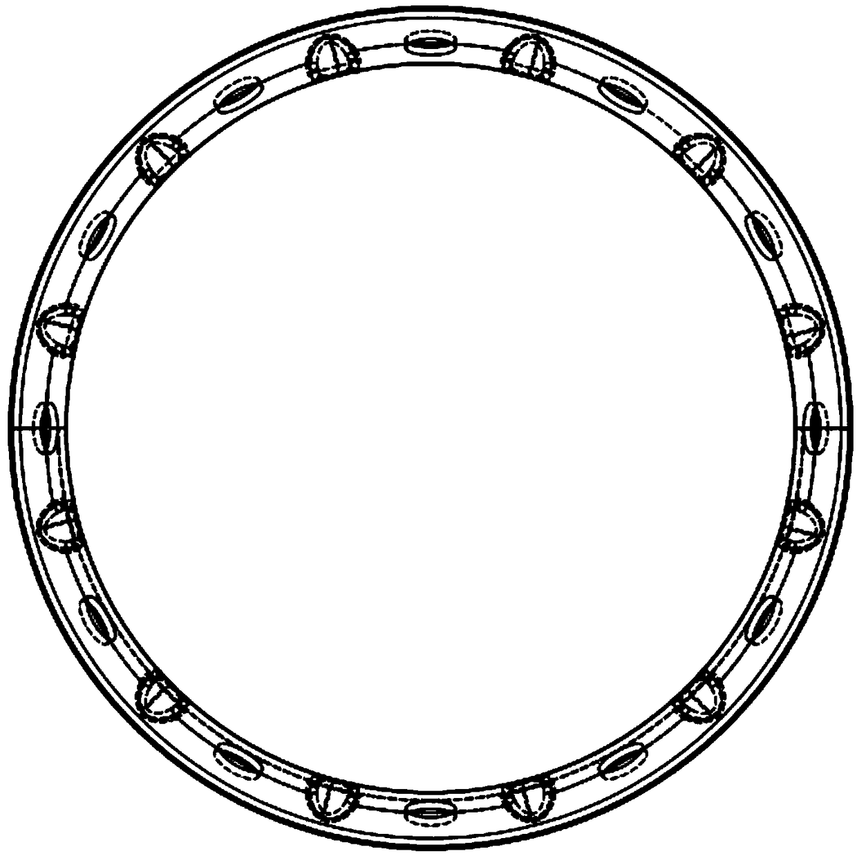
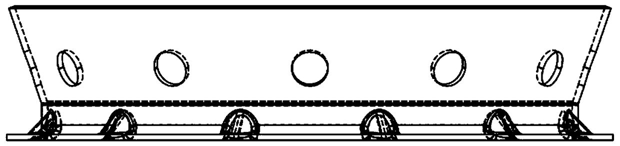
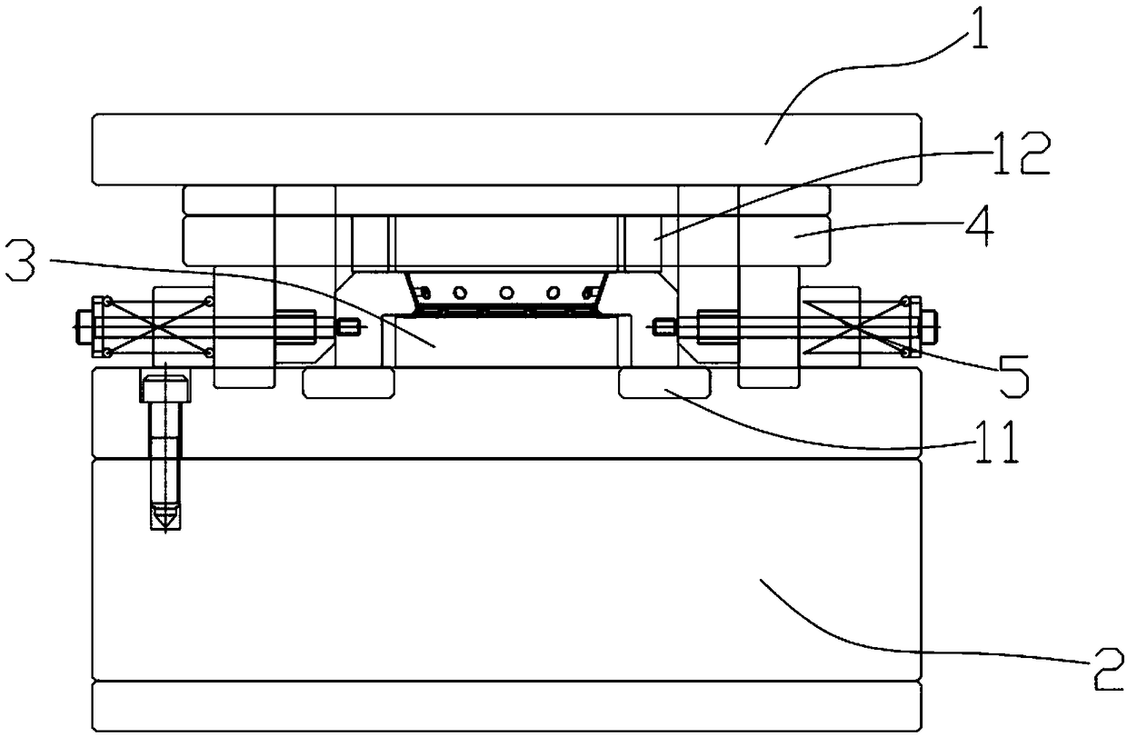
[0027] Such as Figure 3 ~ Figure 8 As shown, the present invention proposes a continuous die for the side punching of an automobile ring disc, including a punching die, a twelve-hole side punching shaping die, and a flanging die arranged in sequence.

[0028] The twelve-hole side punch shaping die includes a first upper template 1 and a first lower template 2, a first placement table 3 is arranged between the first upper template 1 and the first lower template 2, and the first placement The platform 3 is used to place products, the lower part of the first upper template 1 is connected with a positioning platen 4, and the positioning platen 4 is pressed on the first placing platform 3, and the first placing platform 3 is provided with a column shaped body 13, the cylindrical ...


PUM


Abstract

The invention provides a side stamping progressive die for an automotive annular circular disc part. The side stamping progressive die comprises a stamping die, a twelve-hole side stamping sizing dieand a flanging die which are arranged in sequence. The invention further discloses a side stamping process of the side stamping progressive die for the automotive annular circular disc part. The sidestamping process comprises the following steps: S1, raw material stamping: taking a strip-shaped metal plate, and stamping the strip-shaped metal plate to form a circular disc-shaped sheet through a stamping machine; and S2, stretching punching: stamping through a stamping shaping part of a progressive stamping die, punching the center of the circular sheet, and forming a middle cylindrical bulgepart and an annular part at the bottom of the bulge part. The side stamping progressive die is provided with the twelve-hole side stamping sizing die used for simultaneously punching 12 holes, so thatthe side stamping progressive die can simultaneously punch 12 holes in the side wall of a thin workpiece, and therefore the efficiency is improved. Meanwhile, the side stamping progressive die applies force simultaneously to the surroundings of the workpiece, so that the workpiece cannot deform. As the mechanism capable of sizing at the same time is arranged, the side stamping progressive die canensure that one stamping realizes the simultaneous completion of punching and preliminary sizing, and therefore the working efficiency is improved.

Description

technical field [0001] The invention relates to the field of mold processing, in particular to a side-punching continuous mold and a side-punching process for an annular disc part of an automobile. Background technique [0002] With the rapid development of my country's economy, the updating and upgrading of electronics, automobiles and construction machinery is getting faster and faster, and the parts of automobiles have strange shapes, such as attached figure 1 and 2 As shown in the workpiece, the center of the structure is a slope, the side is provided with 12 punching holes, the connection between the vertical part and the bottom is provided with recessed reinforcement holes, and the top or bottom is provided with flanging. It should be stamped according to the traditional mold The method is generally through the steps of stamping, stretching, side punching, flanging, shaping, etc., and is generally stamped through a continuous die, but because the more steps to be proc...

Claims


Application Information

Patent Timeline
Patent Type & Authority Applications(China)
IPC IPC(8): B21D37/10B21D35/00B21D53/88
CPCB21D35/001B21D35/002B21D37/10B21D53/88
Inventor 刘大海
Owner 苏州万荣汽配科技有限公司
Why Eureka
Try Eureka