
Connecting structure and working method of movable ore groove dust removal system

A mobile dust removal and connection structure technology, applied in the direction of loading/unloading, conveyors, conveyor objects, etc., can solve problems affecting the normal operation of mine tank dust removal, poor lateral compensation effect, and derailment of mobile trolleys, so as to prevent deviation and derailment , reduce the amount of maintenance, reduce the effect of labor intensity

Active Publication Date: 2018-12-14
ANGANG STEEL CO LTD
View PDF11 Cites 8 Cited by
  • Summary
  • Abstract
  • Description
  • Claims
  • Application Information

AI Technical Summary

Problems solved by technology

The spring compensator can compensate radially, but the lateral compensation effect is poor
[0007] To sum up, the most critical connection between the mobile dust collection trolley and the mobile unloading vehicle in the mobile dust removal system of the mine trough; so far, in the high dust environment of the transfer station or the mine trough, with the track Wear and tear or mine dust blocking the mobile trolley will still cause the trolley to derail frequently, affecting the normal operation of the mine tank dust removal

Method used


Image

  • Connecting structure and working method of movable ore groove dust removal system
  • Connecting structure and working method of movable ore groove dust removal system
  • Connecting structure and working method of movable ore groove dust removal system

Examples


Embodiment Construction

[0027] The specific embodiment of the present invention will be further described below in conjunction with accompanying drawing:

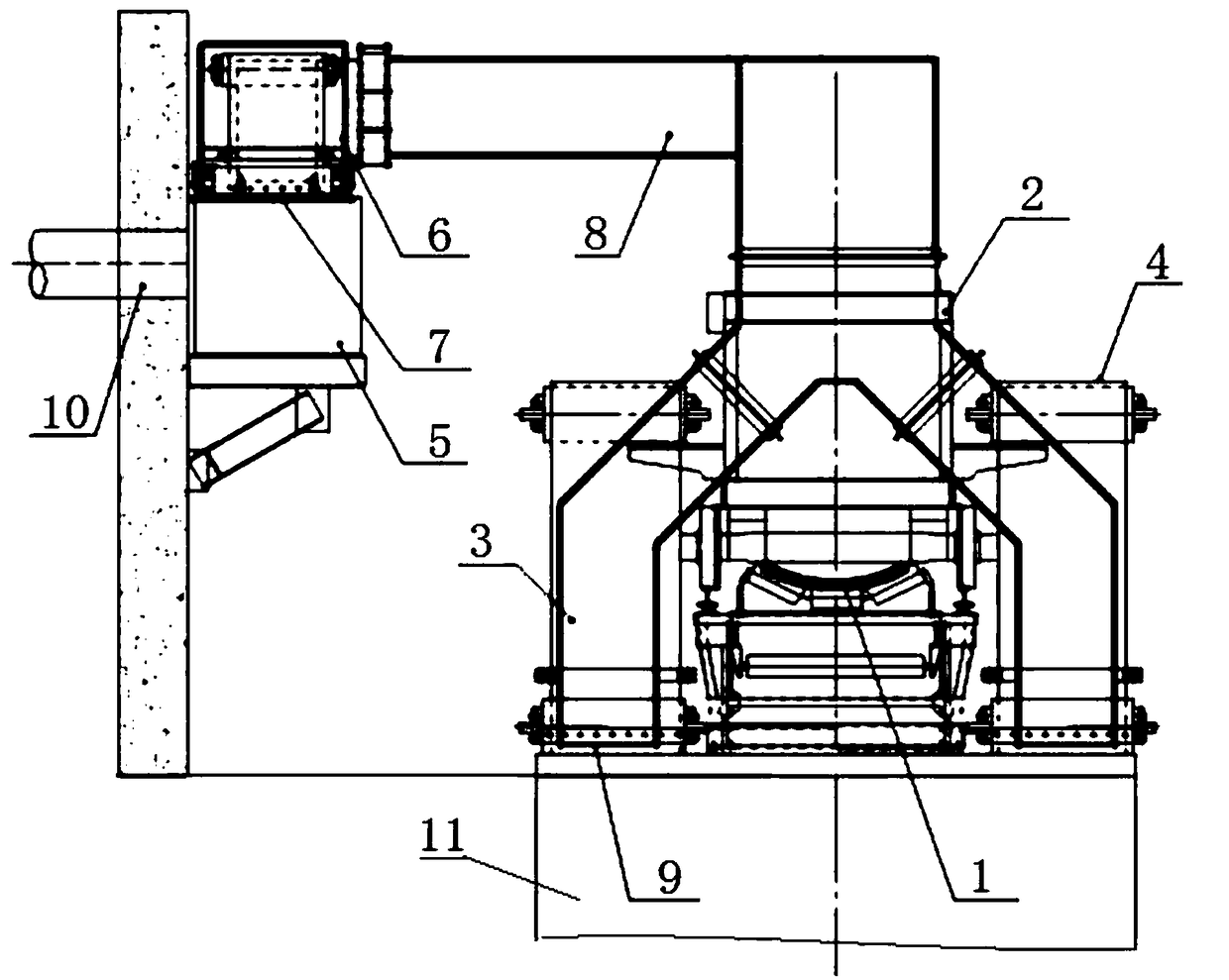
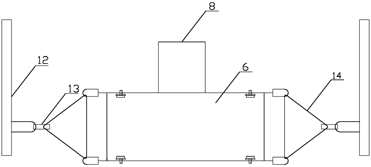
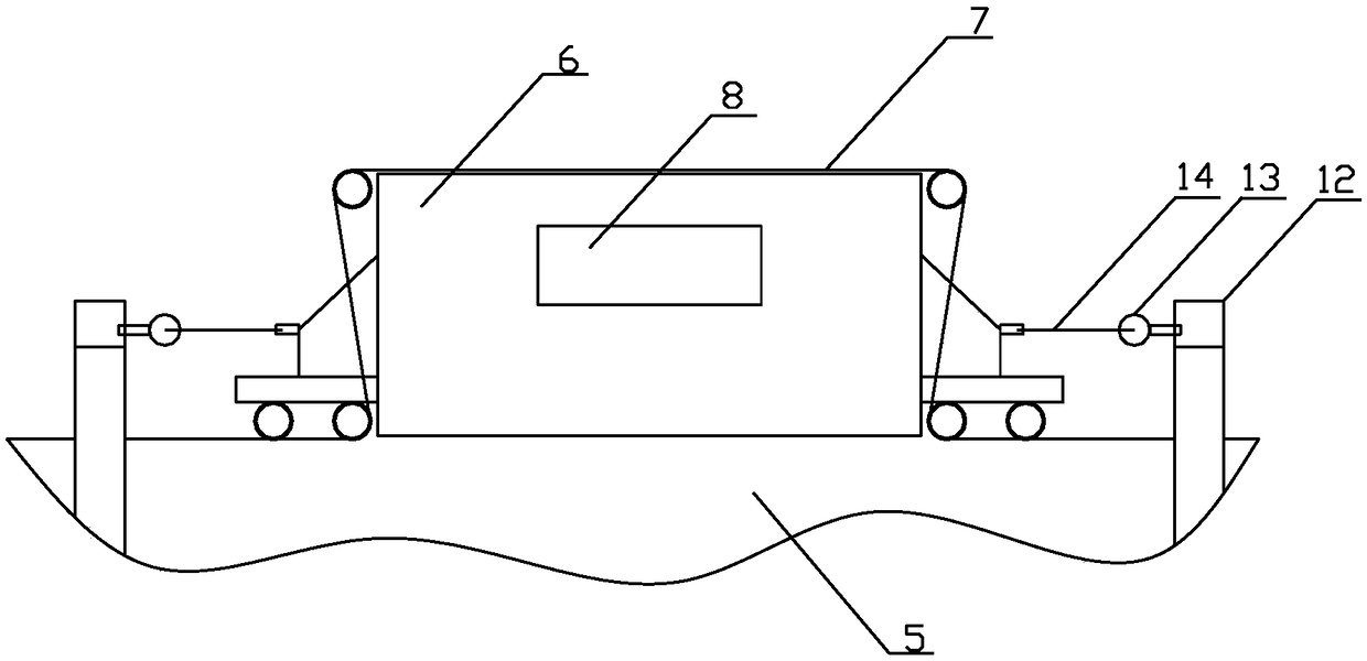
[0028] The connection structure of a mine trough mobile dust removal system described in the present invention, such as figure 1 As shown, the mine trough mobile dust removal system includes a ventilation slot 5, a mobile ventilation trolley 6 and a mobile exhaust pipe 8; the top side of the mine trough 11 is provided with a ventilation trough 5, and the ventilation trough 5 is provided with a mobile ventilation trolley 6, and the mobile ventilation trolley 6 and the ventilation groove 5 are sealed by the ventilation groove sealing belt 7; the head of the discharge belt 1 of the mobile unloading vehicle 2 above the mine trough 11 is provided with a dust cover, and the bottom of the discharge chute 3 on both sides of the mobile discharge vehicle 2 is provided with a The air outlet 9, the mine trough sealing belt 4 is set between the feeding chute 3...


PUM


Abstract

The invention relates to a connecting structure and working method of a movable ore groove dust removal system. The movable ore groove dust removal system comprises a ventilation tank, a movable ventilation trolley and a movable air suction pipe; the ventilation tank is arranged above an ore groove, the movable ventilation trolley is arranged on the ventilation tank, a dust suction hood is arranged at the head part of a discharging belt of a movable discharging trolley above the ore groove, and the bottoms of discharging chutes at the two sides of the movable discharging trolley are each provided with an air suction opening; and the dust suction hood and the air suction openings move along with the movable discharging trolley, and the dust suction hood and the air suction openings are connected with the movable ventilation trolley through the movable air suction pipe. The two ends of the movable discharging trolley are each provided with a fixing frame in the walking direction, the twoends of the movable ventilation trolley are connected with the corresponding fixing frames through steel wire ropes and pulleys respectively, and the movable air suction pipe is in flexible connection with the movable ventilation trolley. According to the connecting structure, the deviation derailment phenomenon of the mobile ventilation trolley can be completely eradicated, the maintenance amount of the ore tank mobile dust removal system is reduced, and meanwhile, the moving speed of the movable ventilation trolley can be increased and the dust removal efficiency in the unit time of the movable ventilation trolley can be improved.

Description

technical field [0001] The invention relates to the technical field of mine trough dust removal, in particular to a connection structure and working method of a mine trough mobile dust removal system. Background technique [0002] Mobile ventilation troughs are widely used in metallurgy, iron and steel, chemical industry, cement, mining industries or in the field of bulk material transfer and ventilation. One of the traditional dust removal methods is to set ventilation troughs on the mine troughs. There are mobile dust collectors on the ventilation troughs. There is a mobile unloading car on it, and the mobile dust collection trolley is connected to the mobile unloading car through the air duct. The unloading car and the mobile dust collection trolley on the mobile ventilation trough run synchronously to collect dust, and the ventilation trough is connected to the dust removal station through the air duct. [0003] The Chinese patent with the notification number CN2201993Y ...

Claims


Application Information

Patent Timeline
IPC IPC(8): B65G69/18B65G47/44
CPCB65G47/44B65G69/18B65G2201/04
Inventor 王永贾一波袁玲王飞徐伟胡绍伟陈鹏
Owner ANGANG STEEL CO LTD
Features
  • Generate Ideas
  • Intellectual Property
  • Life Sciences
  • Materials
  • Tech Scout
  • Unparalleled Data Quality
  • Higher Quality Content
  • 60% Fewer Hallucinations
Learn More