Vial automatic filling machine and filling method thereof

A filling machine and automatic technology, applied in bottle filling, packaging, liquid bottling, etc., can solve problems such as high labor intensity, slow filling speed, and insufficient precision, and achieve the goals of reducing labor, avoiding errors, and improving accuracy Effect

Pending Publication Date: 2018-12-14
东莞市维星流水线机械设备有限公司
View PDF0 Cites 7 Cited by
  • Summary
  • Abstract
  • Description
  • Claims
  • Application Information

AI Technical Summary

Problems solved by technology

[0004] One of the objectives of the present invention is to provide a small bottle automatic filling machine to solve the problems mentioned in the above background technology that the operator stands at both ends of the assembly line for a long time, the labor intensity is very high, the filling speed is slow, and the accuracy is not enough.

Method used


Image

  • Vial automatic filling machine and filling method thereof
  • Vial automatic filling machine and filling method thereof
  • Vial automatic filling machine and filling method thereof

Examples


Embodiment 1

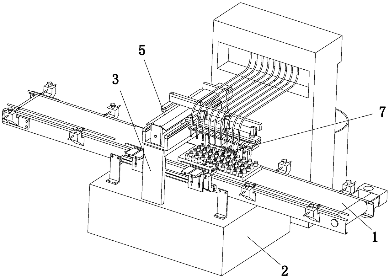
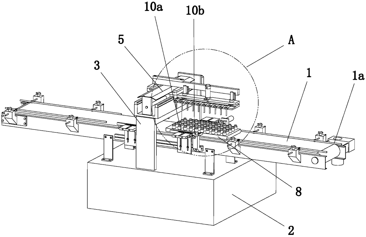
[0035] Such as Figure 1-Figure 7 As shown, a small bottle automatic filling machine includes a conveyor belt 1, a workbench 2, a gantry frame 3, a screw slide table 5, a lifting mechanism, a filling mechanism and a template 8, and the workbench 2 is placed on the conveyor belt 1 Below, the gantry 3 is fixed on the workbench 2, and the gantry 3 is erected on the conveyor belt 1, the screw slide 5 is fixed on the top of the gantry 3, the The lifting mechanism is fixed on the slide table of the screw slide table 5, the filling mechanism is fixed on the moving end of the lifting mechanism, and the filling mechanism can be driven along the vertical direction by the drive of the screw slide table 5. Move horizontally in the direction of the conveying direction of the conveyor belt 1, and the conveyor belt 1 is located within the horizontal movement range of the filling mechanism as the filling area; the template 8 is set corresponding to the bottles used for filling, and there are ...

Embodiment 2

[0045] A method of utilizing the above-mentioned automatic filling equipment to realize non-drip filling, comprising the following steps:

[0046] S1, fill empty bottles on the template 8;

[0047] S2, start the machine, start the filling equipment, and place the template 8 filled with empty bottles on the conveyor belt 1;

[0048] S3. The template 8 is transported to the filling area, and triggers the photoelectric switch 9b arranged on one side of the conveyor belt 1. When the photoelectric switch 9b is touched, the positioning device starts to stop the template 8, and then the clamping device starts to clamp the template 8 left and right. ;

[0049] S4. The lifting device drives all the filling heads 7 down to fill the first batch of empty bottles. After the first batch of filling is completed, the one-way glass valve blocks the filling heads 7; the filling heads 7 move vertically forward to fill The second row, and so on;

[0050] S5. After the filling is completed, the...


PUM


Abstract

Discloses is a vial automatic filling machine and a filling method thereof. The vial automatic filling machine comprises a conveying belt, a workbench, a portal frame, a screw rod sliding table, a lifting mechanism, a filling mechanism and a template. Locating equipment is arranged in a filling area. The advantages of precise filling and high filling speed are achieved. The equipment is used for achieving a dripping-free filling method, during filling, three stages of strokes are adopted, in the first stage of stroke, a movable plate drives an air cylinder to conduct driving, and thus a filling head directly stretches into a filling vial for filling; in the second stage of stroke, the movable plate drives the air cylinder to conduct driving, after filling, the filling head is driven to rise to a vial mouth to stay for a moment; and in the third stage of stroke, the movable plate drives the air cylinder to conduct driving, the filling head completely leaves the vial, and in this way, dripping leakage caused by the operation that after filling, a filling head directly leaves in the past is avoided. 3000 vials are filled hourly at most by a conventional filling machine, after the vialautomatic filling machine is adopted, 8000-15000 vials can be filled hourly, efficiency is improved by 2-5 times, and significant economic benefit is achieved.

Description

technical field [0001] The invention relates to the field of filling equipment and filling methods, in particular to an automatic filling machine for small bottles and a method for realizing non-drip filling by using the equipment. Background technique [0002] The existing small bottle filling machines are all semi-automatic. First, the empty bottles to be filled need to be manually placed on the tray. The person stands next to the assembly line, and then pushes the tray forward through the screw, and the filling head moves down. The empty bottles in the row below are filled, and then the screw pushes the tray to move forward until the filled bottles in the tray are filled. At the end, the labor intensity is very high. Again, it is difficult for the screw to push the material tray to ensure the accuracy of the stroke, and it is impossible to accurately transport the vials to the bottom of the filling head, which leads to the inability to continue the operation, and often ha...

Claims


Application Information

Patent Timeline
IPC IPC(8): B67C3/24B67C3/26
CPCB67C3/24B67C3/26
Inventor 赵维星
Owner 东莞市维星流水线机械设备有限公司
Why Eureka
Try Eureka