
Fiber pipe forming die propelling device

A technology of forming molds and propulsion devices, applied in textiles and papermaking, etc., can solve problems such as wasting labor and affecting production efficiency, and achieve the effects of reducing labor, simple structure, and improving production efficiency

Inactive Publication Date: 2018-12-14
江苏赛图新材料科技有限公司
View PDF5 Cites 0 Cited by
  • Summary
  • Abstract
  • Description
  • Claims
  • Application Information

AI Technical Summary

Problems solved by technology

However, when the forming mold is taken out from the vacuum chamber, due to the long length of the mold, it often requires multiple people to work together to pull the mold out, which not only wastes labor, but also affects production efficiency. Propulsion device inside the evacuated chamber

Method used


Image

  • Fiber pipe forming die propelling device
  • Fiber pipe forming die propelling device
  • Fiber pipe forming die propelling device

Examples


Embodiment Construction

[0015] The present invention will be further described in detail below in conjunction with the accompanying drawings and specific embodiments.

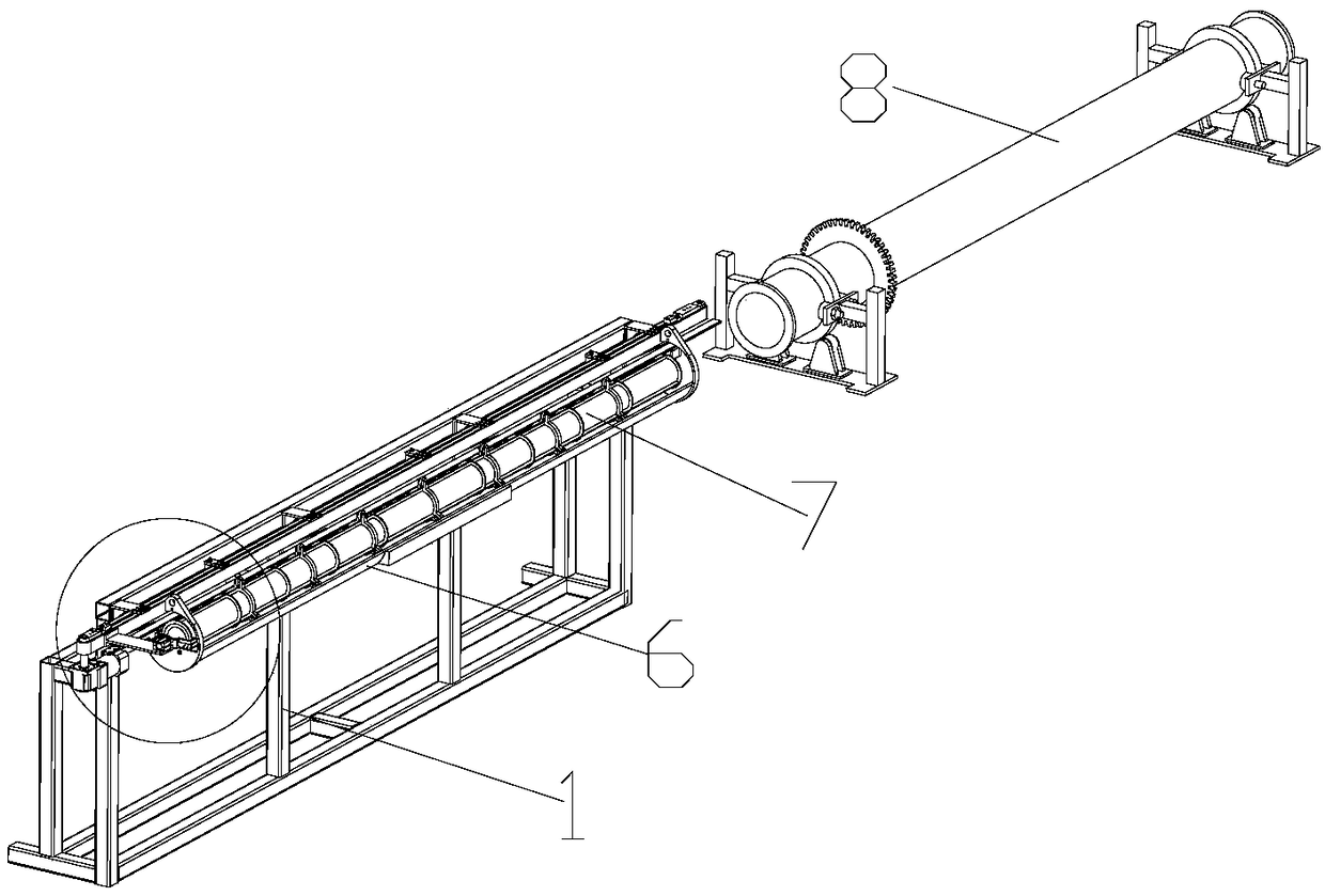
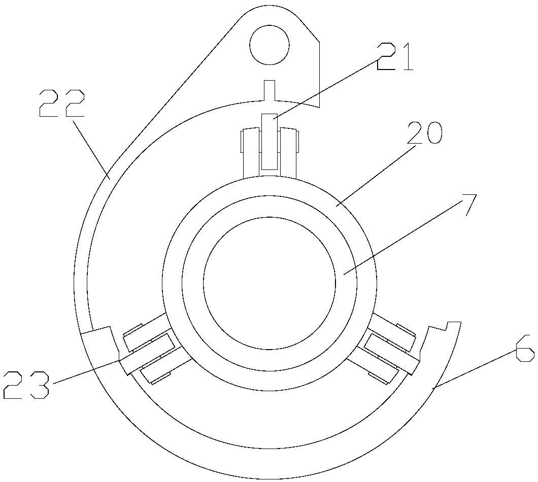
[0016] as attached Figure 1-3 The shown fiber tube forming die propulsion device of the present invention includes a frame 1, a driving mechanism, a push arm 2, a linear slide rail 3, a cylinder 4, clamping jaws 5, a bracket 6, and a ceramic tube forming die 7 and ceramic tube molding equipment 8; the frame 1 is provided with a push arm 2 that can move laterally through a drive mechanism, and the lower end of the push arm 2 is connected with the linear slide rail 3 located on the frame 1, and the movement of the linear slide rail 3 The direction is the same as the pushing direction of the push arm 2; the push arm 2 is provided with a cylinder 4; the cylinder 4 is connected with two jaws 5 for controlling the release or clamping of the two jaws 5; the machine One side of the frame 1 is provided with a bracket 6 parallel to the linear...


PUM


Abstract

The invention relates to a fiber pipe forming die propelling device. A rack is provided with a push arm which can move horizontally through a drive mechanism, and the lower end of the push arm is connected with a linear sliding rail on the rack. A motion direction of the linear sliding rail is the same with a propelling direction of the push arm. The push arm is provided with an air cylinder. Theair cylinder is connected with two clamping jaws, and is used to control the two clamping jaws to get loose or clamp. One side of the rack is provided with a bracket parallel with the linear sliding rail. A ceramic tube molding die is arranged in the bracket through a positioning assembly, and one end of the ceramic tube molding die is in the two clamping jaws. One side of the rack is provided with a ceramic tube molding device, and the ceramic tube molding device is provided with a holding cavity used to hold a ceramic tube molding die. Through a synchronous belt and the linear sliding rail,the ceramic tube molding die is driven to perform accurate linear transmission, and rollers and a guide groove position the ceramic tube molding die, to ensure the ceramic tube molding die to be accurately pushed into the ceramic tube molding device and improve production efficiency of ceramic tubes.

Description

technical field [0001] The invention relates to a molding device for ceramic fiber materials, in particular to a fiber tube molding die propulsion device. Background technique [0002] The ceramic fiber tube can replace the dust bag in the bag filter to filter the dust. Compared with the dust bag, the ceramic fiber tube has good high temperature resistance. In the modern industrial production process, such as metallurgy, building materials, chemical industry, electric power, Various industrial kilns in machinery and other industries emit a large amount of high-temperature dust-containing harmful gases, which seriously pollute the atmospheric environment. Therefore, ceramic fiber tubes with good high-temperature resistance can better meet the needs of the above-mentioned industrial production. [0003] The molding process of the existing ceramic fiber tube needs to mix the ceramic fiber into the slurry first, then pour the slurry into the mold, and then vacuumize the mold to ...

Claims


Application Information

Patent Timeline
Patent Type & Authority Applications(China)
IPC IPC(8): D21J3/04
CPCD21J3/04
Inventor 黄洁
Owner 江苏赛图新材料科技有限公司
Features
  • Generate Ideas
  • Intellectual Property
  • Life Sciences
  • Materials
  • Tech Scout
  • Unparalleled Data Quality
  • Higher Quality Content
  • 60% Fewer Hallucinations
Learn More