Check patentability & draft patents in minutes with Patsnap Eureka AI!

Central well completion tubing string for gaslift production and gaslift construction method

A well completion string and gas lift technology, which is applied in the direction of earthwork drilling, wellbore/well components, production fluid, etc., can solve the problems of wellbore fluid accumulation, short validity period, and high construction risk, so as to improve the efficiency of gas lift and benefit The effect of production management

Inactive Publication Date: 2018-12-14
CHINA PETROLEUM & CHEM CORP +1
View PDF6 Cites 8 Cited by
  • Summary
  • Abstract
  • Description
  • Claims
  • Application Information

AI Technical Summary

Problems solved by technology

[0005] (1) The construction period of the completion string under the pressure operation is nearly 10 days, the cost of a single operation is nearly 1 million, and the construction risk is high. How to reduce the number of replacement of the completion string is an urgent problem to be solved;
[0006] (2) Almost all gas wells have the law of pressure attenuation. When the gas well is produced for a certain period of time, the reservoir pressure of the gas well will drop, and the completion string that was originally run can not meet the current critical liquid-carrying requirements, and fluid accumulation will occur in the wellbore , thereby affecting the production of gas wells;
[0007] (3) If the effusion will reach a certain level, the bottom of the original completion string will be flooded, and conventional nitrogen gas lift, foam drainage and other processes will have a short validity period, and multiple investments will lead to huge costs

Method used


Image

  • Central well completion tubing string for gaslift production and gaslift construction method
  • Central well completion tubing string for gaslift production and gaslift construction method
  • Central well completion tubing string for gaslift production and gaslift construction method

Examples


Embodiment Construction

[0040] The present invention will be further described below in conjunction with accompanying drawing.

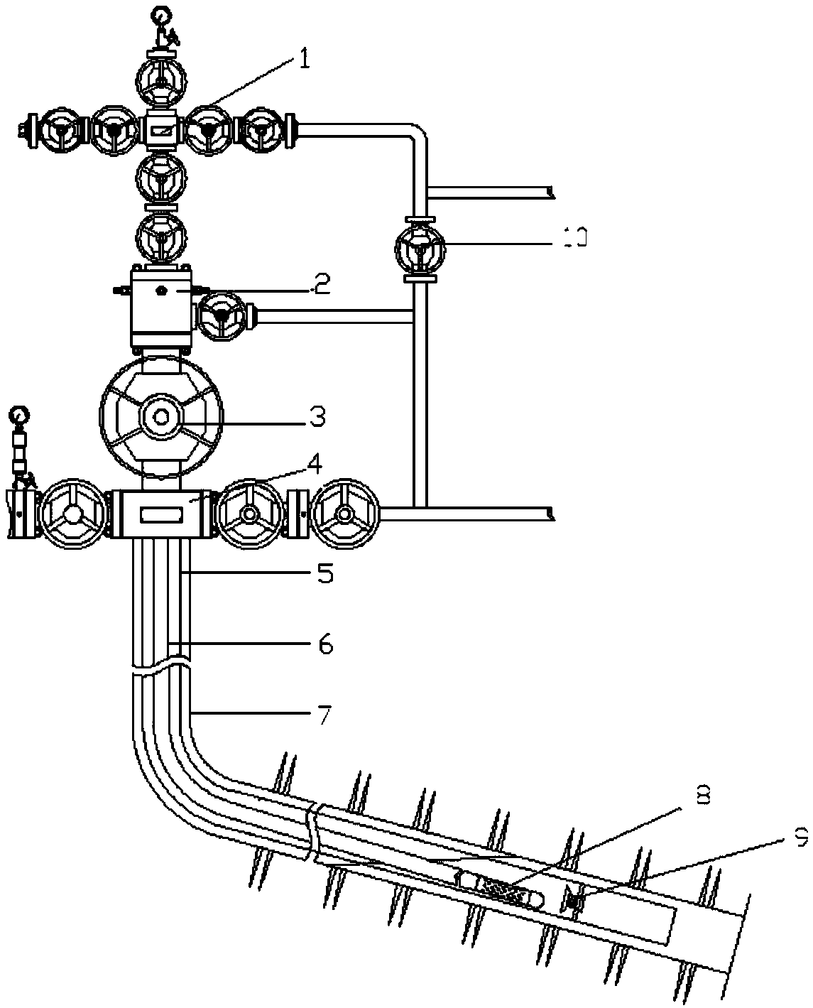
[0041] Such as figure 1As shown, this embodiment provides a central tube completion production string, which includes an external hanger 2, a completion string 5 for snubbing operations, a coiled tubing 6, a plug and a plugging rod, and the coiled tubing 6 The upper end is sealed with the external hanger 2 and is suspended on the external hanger. The external hanger is installed on the upper part of the No. 1 gate valve 3 at the wellhead, and the No. 1 valve 3 at the wellhead is installed above the oil pipe head 4 at the wellhead. The operation completion string 5 is suspended in the tubing head through the hanger. The coiled tubing 6 is suspended 2 by an external hanger and installed in the completion string 5 for hot work. The bottom of the coiled tubing 6 is connected to a plug 8. When the string is lowered, the plug plugs the coiled tubing. The string realizes complet...


PUM


Abstract

The invention discloses a central well completion tubing string for gaslift production and a gaslift construction method. The central well completion tubing string comprises a pressurized well completion oil pipe, an external suspension device, a continuous oil pipe and a blocking device, a working annulus is arranged between the continuous oil pipe and the pressurized well completion oil pipe, the bottom of the continuous oil pipe is connected with the blocking device, the external suspension is provided with a liquid exhausting channel and the work annulus, the liquid exhausting channel is connected with a bypass flange, and the bottom of the pressurized well completion oil pipe is connected with a check valve. The external suspension device is provided with the bypass flange which can serve as a production liquid exhaust channel, the smaller annulus of continuous oil pipe and the pressurized well completion oil pipe provides a relatively low critical liquid flow for a gas producingwell, and a channel is provided for continuous production under a relatively low output of the gas producing well; and when liquid is accumulated in the pressurized well completion oil pipe, nitrogenis extruded into the continuous oil pipe, the check valve is closed, liquid accumulated in the pressurized well completion oil pipe can be exhausted out of a shaft effectively, and influence of accumulated liquid in the shaft on product of the gas producing well can be reduced.

Description

technical field [0001] The invention relates to the field of petroleum and natural gas, in particular to a central completion pipe string for gas lift production and a gas lift construction method. Background technique [0002] In the process of gas reservoir development, the high-speed gas-liquid two-phase flow in the wellbore scours the casing and the casing head, tubing head and other components on the upper part of the casing for a long time, which has certain well control safety risks; If the critical liquid-carrying flow rate cannot carry formation water well out of the wellbore, wellbore fluid accumulation will occur, which will affect the production of the gas well. Therefore, generally after the completion of the gas well test, the 2 7 / 8 or 2 3 / 8 Conventional tubing for well completions. [0003] However, when the gas well is produced for a certain period of time, as the formation pressure drops, the gas flow rate decreases, and the liquid-carrying capacity...

Claims


Application Information

Patent Timeline
Patent Type & Authority Applications(China)
IPC IPC(8): E21B43/00
CPCE21B43/122E21B43/123
Inventor 陈建达徐冠军王大江吴魏孙志扬费成俊刘军夏绪波张正道喻建川
Owner CHINA PETROLEUM & CHEM CORP
Features
  • R&D
  • Intellectual Property
  • Life Sciences
  • Materials
  • Tech Scout
  • Unparalleled Data Quality
  • Higher Quality Content
  • 60% Fewer Hallucinations
Learn More