Gas engine electrically-controlled gas injection valve testing device and testing method thereof

A technology of gas injection valve and gas engine, applied in the direction of measuring device, testing of mechanical parts, testing of fluid tightness, etc., can solve compressibility, pressure fluctuation, large injection frequency, flow difference, single injection volume and injection problems with rules

Pending Publication Date: 2018-12-14
NO 711 RES INST CHINA SHIPPING HEAVY IND GRP
View PDF13 Cites 8 Cited by
  • Summary
  • Abstract
  • Description
  • Claims
  • Application Information

AI Technical Summary

Problems solved by technology

Ideally, when the injection pulse width is the same, the gas volume of each gas injection valve is the same; but in reality, there are flow differences between valves, and a single valve also has flow drift, so it is necessary to Consistency and stability of gas injection valves are measured
[0004] Therefore, in the development and application of electronically controlled gas injection valve products, it is necessary to conduct experiments to verify its performance parameters. However, due to the compressibility of gas, large pressure fluctuations, and high injection frequency, the single Injection volume and injection pattern are very difficult, and there is no special device for testing electronically controlled gas injection valves on the market

Method used


Image

  • Gas engine electrically-controlled gas injection valve testing device and testing method thereof

Examples


Embodiment Construction

[0023] The present invention will be further described below in conjunction with the accompanying drawings.

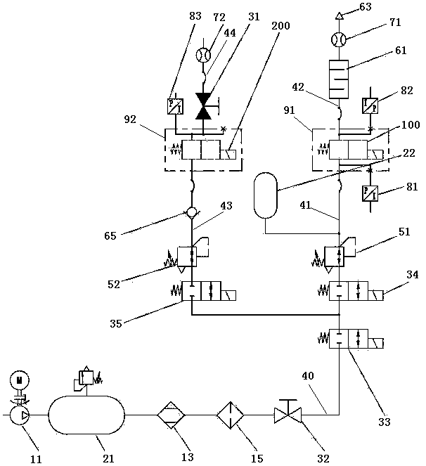
[0024] figure 1 A schematic structural view of an embodiment of the gas engine electronically controlled gas injection valve testing device of the present invention is shown. see figure 1 According to an embodiment of the present invention, the gas engine electronically controlled gas injection valve testing device includes an air supply mechanism, a flow testing mechanism and a leakage testing mechanism.

[0025] The air supply system is used to provide dry and pure air with a certain pressure to the flow test mechanism and leakage test mechanism. The air supply mechanism includes an air source 11 , a first air storage tank 21 , a dryer 13 , a filter 15 , a second stop valve 32 , a third stop valve 33 and a main pipeline 40 . The inlet of the main pipe 40 communicates with the outlet of the air source 11, and the outlet of the main pipe 40 constitutes the outlet of...


PUM


Abstract

The invention discloses a gas engine electrically-controlled gas injection valve testing device. The device comprises an air supply mechanism and a flow testing mechanism; the flow testing mechanism comprises a first branch pipeline, a second branch pipeline, a first pressure adjusting valve, a buffer, a first flowmeter, a first pressure sensor, a second pressure, and a first workpiece table for placing a to-be-tested electrically-controlled gas injection valve; an inlet of the first branch pipeline is communicated with the air supply mechanism, the first pressure adjusting valve is arranged on the first branch pipeline, the outlet of the first branch pipeline is used for communicating the gas inlet of the electrically-controlled gas injection valve; the first pressure sensor is arranged on the first branch pipeline; the inlet of the second branch pipeline is used for communicating the gas outlet of the electrically-controlled gas injection valve; the second pressure sensor, the bufferand the first flowmeter are orderly arranged on the second branch pipeline along a gas conveying direction. The invention further discloses a testing method of a gas engine electrically-controlled gas injection valve testing device. The steady-state flow and the dynamic flow of the electrically-controlled gas injection value can be tested.

Description

technical field [0001] The invention relates to a test device and a test method for testing the performance of an electronically controlled gas injection valve of a gas engine. Background technique [0002] As the core component of the gas engine gas supply system, the function of the electronically controlled gas injection valve is to inject a certain amount of natural gas into the engine intake port or cylinder with a certain pressure to mix with air. The gas intake volume is mainly controlled by adjusting the injection pulse Its performance is directly related to the performance, combustion and emission of the engine. The structure of the existing common gas injection valve can refer to the records of the Chinese invention patent application with the application date of August 31, 2016 and the application number of 201610771921.7. An existing electronically controlled gas injection valve includes a valve body, an electromagnet and a valve core assembly. Both the electro...

Claims


Application Information

Patent Timeline
Patent Type & Authority Applications(China)
IPC IPC(8): G01M13/00G01M3/02G01M3/28
CPCG01M3/025G01M3/2876G01M13/00
Inventor 赵中祥孙鹏张通唐敏
Owner NO 711 RES INST CHINA SHIPPING HEAVY IND GRP
Why Eureka
Try Eureka