Detection device of excircular surface defect of tapered roller

A technology for tapered roller and defect detection, applied in measuring devices, material analysis through optical means, instruments, etc., can solve problems affecting bearing quality and quality, low detection efficiency, low work efficiency, etc., and achieve high-speed and reliable automatic detection , The structure of the device is simple, and the effect of cost detection is realized

Inactive Publication Date: 2018-12-14
TIANJIN UNIV
View PDF4 Cites 2 Cited by
  • Summary
  • Abstract
  • Description
  • Claims
  • Application Information

AI Technical Summary

Problems solved by technology

However, the processing of the existing rolling elements generally requires dozens of processes, and some surface defects often appear during the processing, which seriously affects the quality and quality of the bearing and must be controlled.
Therefore, before the automatic assembly of rolling bearings, it is necessary to first detect the surface defects of the key parts of the rolling elements to avoid surface defects caused by processing, which will eventually cause serious damage to the mechanical device
[0003] At present, most bearing manufacturers use manual inspection to detect rolling element surface defects. This method is labor-intensive, low-efficiency, high-cost, and is easily affected by factors such as the technical quality, experience, visual resolution and fatigue of inspectors.
Some detection methods such as infrared flaw detectors are greatly affected by the external environment or operators, and the detection efficiency is low
Ultrasonic detection has strict requirements on the distance from the ultrasonic sensor to the workpiece and the positioning of the sensor, which is difficult to achieve in the factory environment

Method used


Image

  • Detection device of excircular surface defect of tapered roller
  • Detection device of excircular surface defect of tapered roller
  • Detection device of excircular surface defect of tapered roller

Examples


Embodiment 1

[0022] Example 1: Example when the rolling elements are rollers

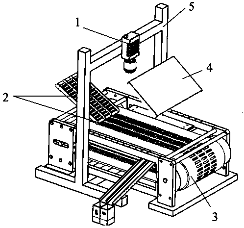
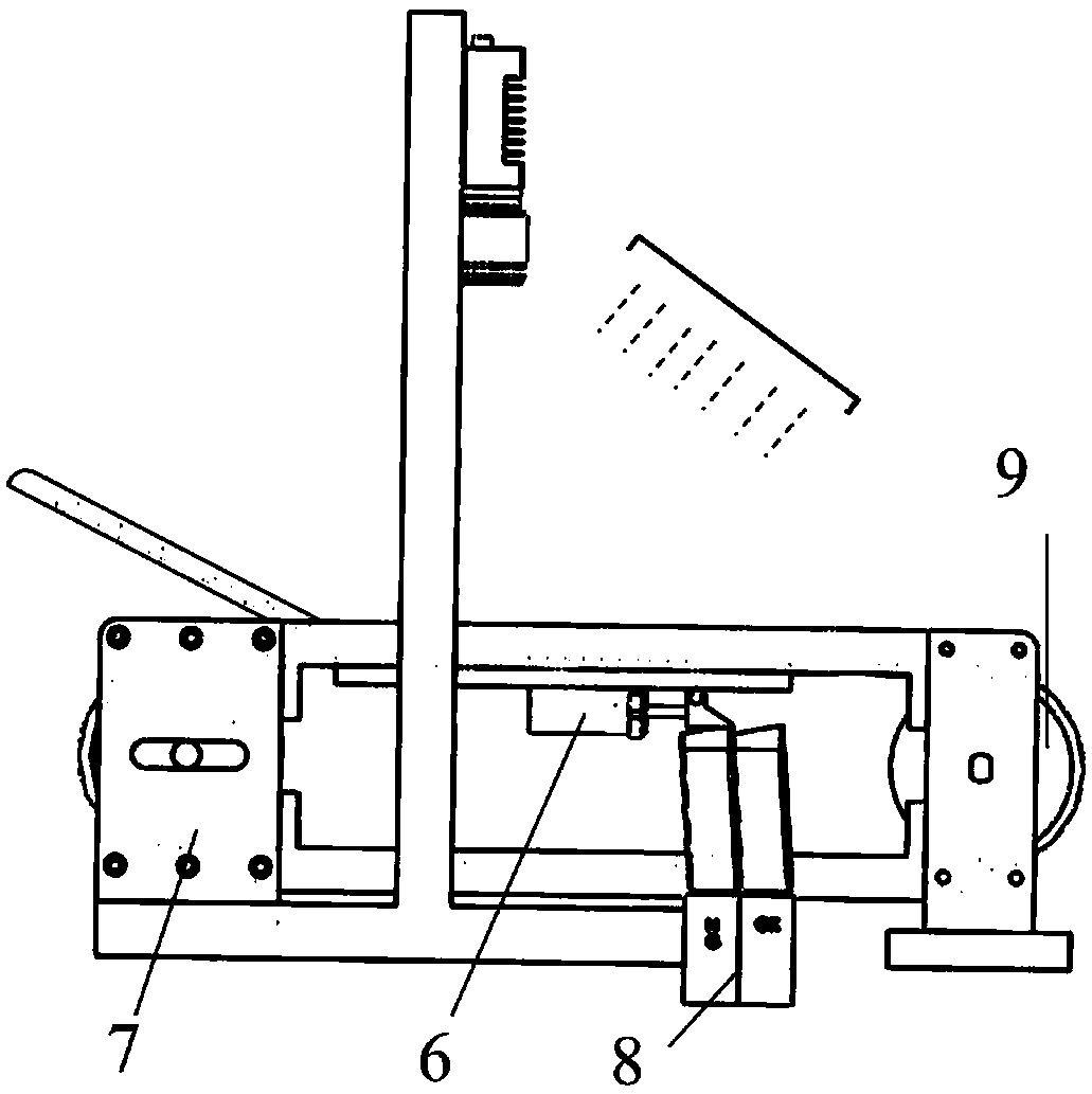
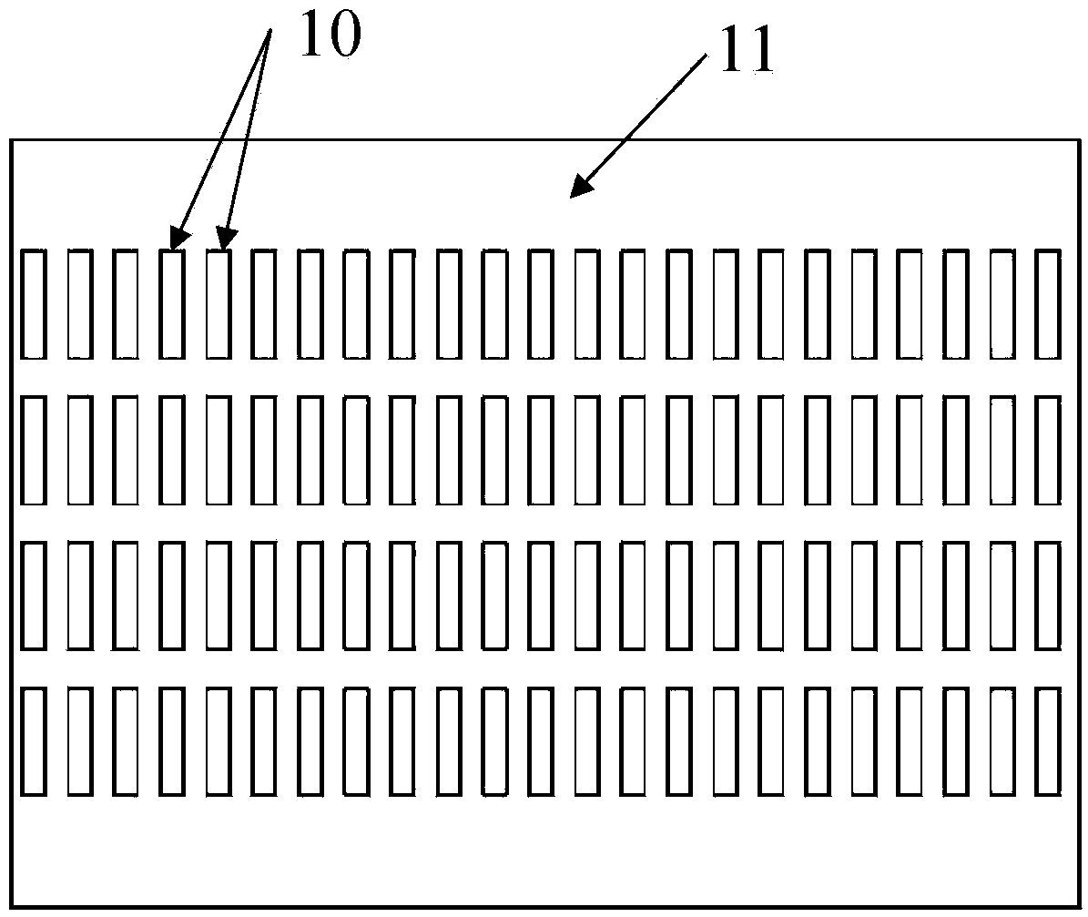
[0023] Such as figure 1 As shown, the automatic detection device for the full surface defect of the bearing roller provided in this embodiment is mainly composed of a camera 1 , a conveyor belt 3 with a slot array structure, a light source 4 , a rejecting device 6 and an electric drum 9 . The specific process of detection is as follows: firstly, the detection device undertakes the production end of the roller, and the rolling body 2 to be tested is a bearing roller. Conveyed to the slot array structure conveyor belt 3 by the feeder, the motorized roller 9 drives the slot array structure conveyor belt, using the friction between the rollers and the bottom plate 12 below the conveyor belt 11 to make the rollers turn over and pass through the slots 10 continuously Below the camera, the image of the full surface of the roller is collected by the camera, and then the computer processes the image in real time to obta...

Embodiment 2

[0028] Example 2: Example when the rolling elements are balls

[0029] Such as Figure 10 As shown, the automatic detection device for full-surface defects of bearing balls provided in this embodiment is mainly composed of a camera 1 , a conveyor belt 3 with a slot array structure, a light source 4 and an electric drum 9 . In order to improve the detection efficiency, the conveyor belt has four S-shaped slot channels. The active rolling diameter is larger than the driven rolling, so that the conveyor belt has a certain slope. The specific process of detection is as follows: firstly, the detection device undertakes the ball production end, and the rolling body 2 to be tested is a bearing ball. The feeder controls the balls to be delivered to the slot array structure conveyor belt 3 one at a time, and the electric drum 9 drives the slot array structure conveyor belt to reverse. The balls use gravity to roll freely in the slots. The roller reverses and cooperates with the fric...

Embodiment 3

[0031] Example 3: Example when the rolling elements are tapered rollers

[0032] Such as Figure 11As shown, the automatic detection device for outer surface defects of bearing tapered rollers provided in this embodiment is mainly composed of a camera 1 , an electric turntable 17 , a turntable 16 with a trapezoidal hole array structure, a light source 4 and a base 12 . Based on the characteristics of the geometric structure of the tapered rollers, an annular turntable with a conical hollow groove is designed to ensure the uniform rotation of the tapered rollers by means of rotation. The specific process of detection is as follows: First, the detection device undertakes the tapered roller production end, and the rolling element 2 to be tested is a bearing tapered roller. The feeder transports the tapered rollers to the trapezoidal hole array structure turntable 16, and the electric turntable 17 drives the trapezoidal hole array structure turntable 16 to rotate, using the frict...


PUM


Abstract

The invention relates to a detection device of an excircular surface defect of a tapered roller. The detection device comprises a camera, a light source, a conveying mechanism and a driving mechanismfor driving the conveying mechanism to move, wherein the camera is used for shooting an image of a rolling body in the rolling process under coordination of the light source; the detection device is characterized in that at least one hole slot channel matched with the size and the position of a rolling body to be detected is formed in the conveying mechanism along the advancing direction of the rolling body to be detected; the conveying mechanism is placed on a stationary bottom plate; the rolling body to be detected is the tapered roller; the conveying mechanism is a trapezoidal hole slot array structure turnplate; the driving mechanism is an electric turntable; the hole slot channel consists of a plurality of trapezoidal hole slots which are formed around the circular center of the turnplate as a center; the trapezoidal hole slots are designed according to the size and the geometric structural features of the tapered roller; when the electric turntable drives the trapezoidal hole slot array structure turnplate to rotate, due to a friction between the tapered roller and the bottom plate, the tapered roller overturns in the hole slot.

Description

technical field [0001] The invention relates to an automatic detection device for defects on the entire surface of a rolling body. Background technique [0002] Rolling bearings are widely used in the fields of machinery, electric power, petrochemical, metallurgy, aerospace and military industries. The rolling element is the core element in the rolling bearing. Due to its existence, there is rolling friction between the relative moving surfaces. The types of rolling elements include balls, cylindrical rollers, tapered rollers, needle rollers, etc. The quality of rolling elements has a vital impact on the precision, motion performance, and service life of rolling bearings, and has a major impact on the motion state of the whole machine and even the entire production line. However, the processing of the existing rolling elements generally requires dozens of procedures, and some surface defects often appear during the processing, which seriously affects the quality and qualit...

Claims


Application Information

Patent Timeline
Patent Type & Authority Applications(China)
IPC IPC(8): G01N21/952
CPCG01N21/952
Inventor 张效栋朱琳琳闫宁
Owner TIANJIN UNIV
Why Eureka
Try Eureka