Eureka AIR delivers breakthrough ideas for toughest innovation challenges, trusted by R&D personnel around the world.

Power failure detection delay circuit for engine control system

A technology of control system and delay circuit, applied in power supply testing, circuit devices, emergency protection circuit devices, etc., can solve problems such as inability to popularize and apply, high risk, cumbersome work, etc., and achieve the ability of flexible design and emergency situation Strong, work-reducing effect

Active Publication Date: 2018-12-14
XIAN AEROSPACE PROPULSION TECH INST
View PDF4 Cites 2 Cited by
  • Summary
  • Abstract
  • Description
  • Claims
  • Application Information

AI Technical Summary

Problems solved by technology

If the zero adjustment work is performed before each power-on, the work is cumbersome and dangerous; if the system returns to the electrical and mechanical zero before each power-off, in special cases, when the power is cut off halfway, it still needs to be re-zeroed , this method cannot be promoted and applied to the project

Method used


Image

  • Power failure detection delay circuit for engine control system
  • Power failure detection delay circuit for engine control system
  • Power failure detection delay circuit for engine control system

Examples


Embodiment Construction

[0031] The present invention will be described in detail below with reference to the accompanying drawings and examples.

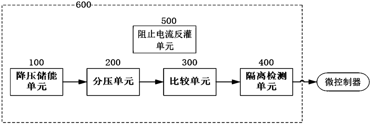
[0032] The invention provides a power-down detection delay circuit for the engine control system, which is applied to the missile servo system. The power supply of the control circuit on the missile generally uses a +28V battery, and each subsystem is converted to the required voltage by DC-DC. The voltage value is used. The power-down detection delay circuit 600 includes a step-down energy storage unit 100, a voltage dividing unit 200, a comparison unit 300, an isolation detection unit 400, and prevents the current backfeeding unit 500, such as figure 1 shown.

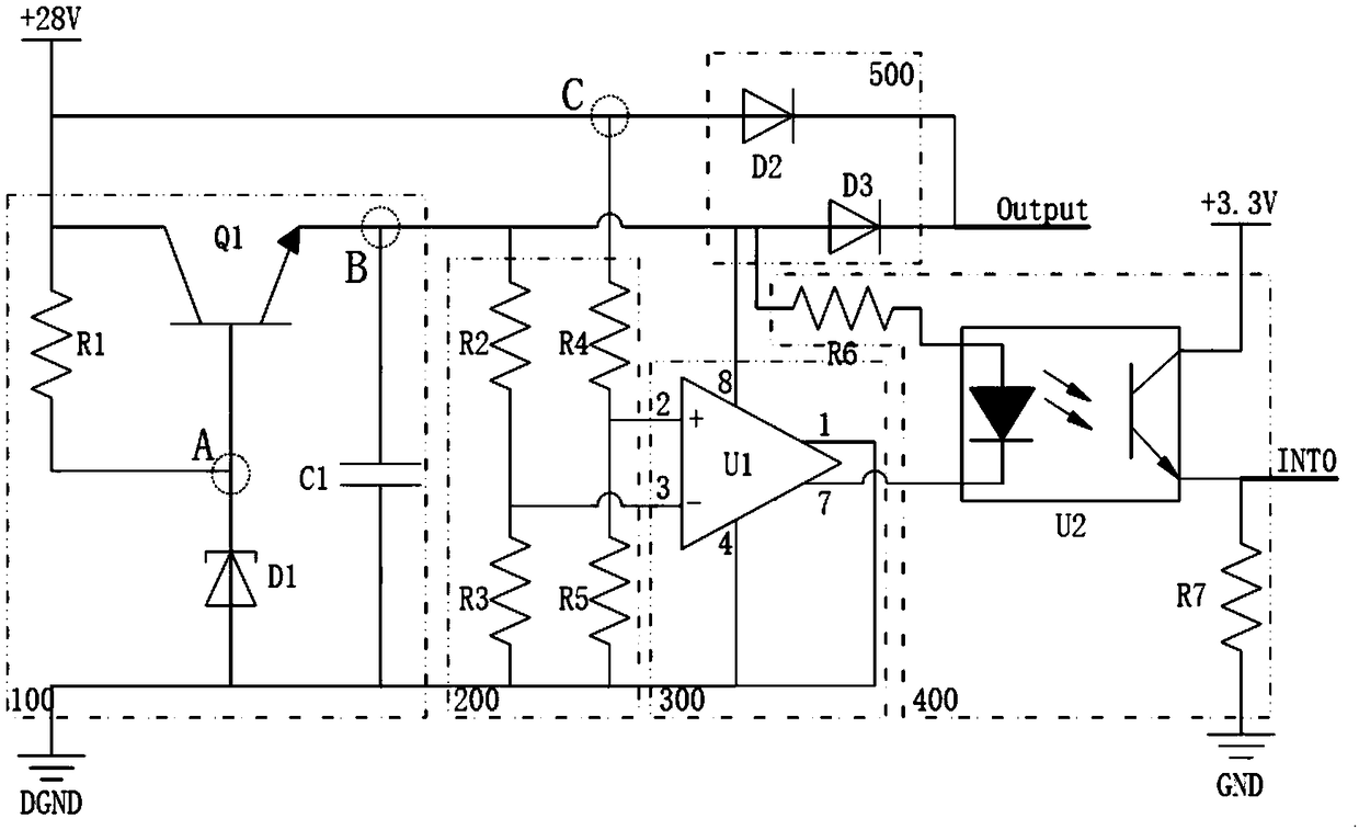
[0033] The connection relationship of each part is as figure 2 Shown:

[0034] The step-down energy storage unit 100 is composed of a resistor R1, a transistor Q1, a Zener diode D1, and an energy storage capacitor C1; the collector of the transistor Q1 and one end of the resistor R1 are connec...


PUM


Abstract

The invention provides a power failure detection delay circuit for an engine control system. The power failure detection delay circuit comprises a voltage reduction and energy storage unit, a voltagedivision unit, a comparison unit, an isolation detection unit and a current reverse-pouring prevention unit; the voltage reduction and energy storage unit is used for charging itself by utilizing a power supply and supplying power when the voltage reduction and energy storage unit is powered down; the voltage division unit is used for reducing the output voltage of the voltage reduction and energystorage unit and the voltage of the power supply and then outputting the voltages to the comparison unit; the comparison unit compares the received two voltage magnitudes and outputs a comparison result to the isolation detection unit; the isolation detection unit is used for isolating and transmitting the comparison result to a microcontroller, and provides a high-level signal or a low-level signal to the input end of the microcontroller for providing a basis for carrying out power failure judgment on the basis of rising edges for the microcontroller; and the current reverse-pouring prevention unit is used for preventing the power supply from being in reversed connection and preventing the voltage reduction and energy storage unit from reversely pouring to the power supply in power down.According to the power failure detection delay circuit, the circuit is simple, the power supply power down can be detected, and delayed power supply can be carried out in a short time.

Description

technical field [0001] The invention relates to the technical field of battery power protection, in particular to a power-down detection delay circuit for an engine control system. Background technique [0002] The modern missile servo system requires high reliability in the application environment. In some special cases (such as the position sensor and the output shaft are not synchronously rotated, and there is a certain proportional relationship), the current position information needs to be stored when the power is off, and the power-off detection The delay circuit becomes a crucial part of the control circuit of the engine control system. [0003] In a special solid engine control system, the flow switch valve is driven by a motor and a reducer with a small reduction ratio. Due to space constraints, the position sensor (resolver) cannot be directly installed on the output shaft, but is installed at the output end of the servo motor. There is a certain proportional rela...

Claims


Application Information

Patent Timeline
Patent Type & Authority Applications(China)
IPC IPC(8): G01R31/40H02J9/06H02H11/00
CPCG01R31/40H02H11/002H02J9/06
Inventor 张竟飞文建刚何颐周亚军张格张环宇胡博杨森
Owner XIAN AEROSPACE PROPULSION TECH INST
Why Eureka
Eureka Blog
Learn More