Aerostat-based occultation detection system and method
A detection system and processor technology, applied in the field of space detection, can solve the problems of inability to achieve key observations in key areas, less allocation of occultation channels, and high launch costs, and achieve the effect of real-time and flexible configuration
- Summary
- Abstract
- Description
- Claims
- Application Information
AI Technical Summary
Problems solved by technology
Method used
Image
Examples
Embodiment 1
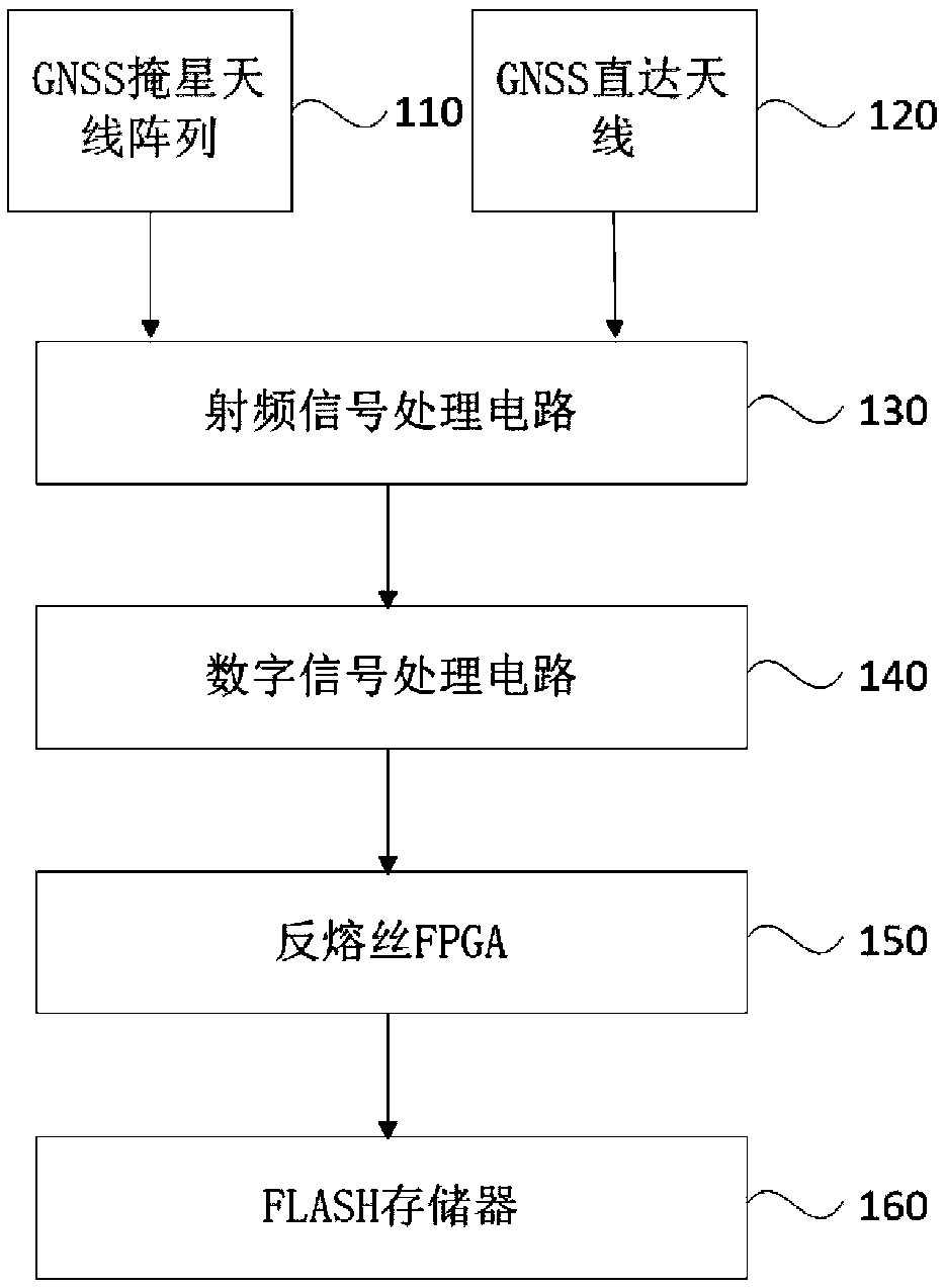
[0050] figure 1 A structural block diagram of an aerostat-based occultation detection system provided for Embodiment 1 of the present invention. This embodiment can be applied to quickly switch between ionospheric occultation detection and atmospheric occultation detection functions through telemetry commands to achieve real-time and flexible Configure the occultation channel to focus on the observation of key areas. Such as figure 1 As shown, the system includes:
[0051] GNSS occultation antenna array 110 , GNSS direct antenna 120 , radio frequency signal processing circuit 130 , digital signal processing circuit 140 , antifuse FPGA 150 and FLASH memory 160 .
[0052] It should be noted that the occultation detection system provided by the embodiment of the present invention can be configured on an aerostat to realize the above-mentioned occultation detection function, wherein, in particular, the aerostat can be an airship (near-space airship or space airship )Wait. Typi...
Embodiment 2
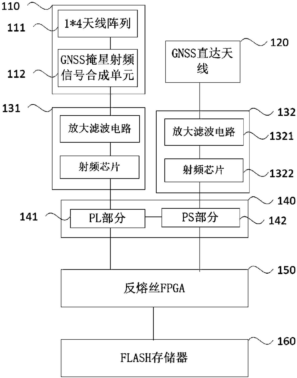
[0068] Such as Figure 2a As shown, in this embodiment, a specific structural block diagram of an aerostat-based occultation detection system is given.
[0069]In the embodiment of the present invention, optionally, based on the above-mentioned occultation detection system, the radio frequency signal processing circuit specifically includes: a GNSS occultation radio frequency signal processing subcircuit 131 and a GNSS direct radio frequency signal processing subcircuit 132 .
[0070] The GNSS occultation radio frequency signal processing subcircuit 131 is connected to the GNSS occultation antenna array 110 and the digital signal processing circuit 140 respectively, and the GNSS direct radio frequency signal processing subcircuit 132 is connected to the GNSS direct antenna 120 and the digital signal processing subcircuit 132 respectively. The processing circuit 140 is connected, and the GNSS occultation radio frequency signal processing sub-circuit 131 and the GNSS direct radi...
Embodiment 3
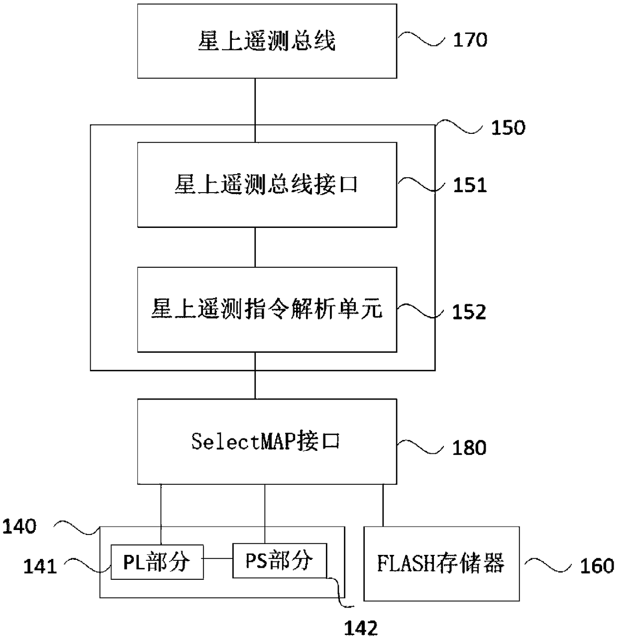
[0088] image 3 It is a flow chart of an aerostat-based occultation detection method provided in Embodiment 3 of the present invention, which is applied to the aerostat-based occultation detection system described in any embodiment of the present invention. This embodiment is applicable to the situation where the ground telemetry bus command is received through the antifuse FPGA, bit stream files with different functions are selected to be loaded to the SOC processor by analyzing the command, and the functions of ionospheric occultation detection and atmospheric occultation detection are quickly switched. Such as image 3 As shown, the method includes:
[0089] Step 310, acquiring and analyzing ground telemetry instructions;
[0090] In this embodiment, when a power-on start command is detected, the antifuse FPGA acquires the ground telemetry command and performs command analysis on the ground telemetry command.
[0091] Step 320, according to the command analysis result, l...
PUM
 Abstract
Description
Claims
Application Information
 - R&D
- Intellectual Property
- Life Sciences
- Materials
- Tech Scout
- Unparalleled Data Quality
- Higher Quality Content
- 60% Fewer Hallucinations
Browse by: Latest US Patents, China's latest patents, Technical Efficacy Thesaurus, Application Domain, Technology Topic, Popular Technical Reports.
© 2025 PatSnap. All rights reserved.Legal|Privacy policy|Modern Slavery Act Transparency Statement|Sitemap|About US| Contact US: help@patsnap.com


