

Buzzer driving circuit and corresponding buzzer driving method
A driving circuit and driving method technology, applied in the field of buzzer driving and buzzer driving circuit, can solve the problems of broken pins, inconsistent buzzer loudness, poor consistency, etc., to reduce power consumption, stable current performance, Small device size
- Summary
- Abstract
- Description
- Claims
- Application Information
AI Technical Summary
Problems solved by technology
Method used
Image

Examples
Embodiment Construction
[0062] In order to make the object, technical solution and advantages of the present invention clearer, the present invention will be further described in detail below in conjunction with specific examples.
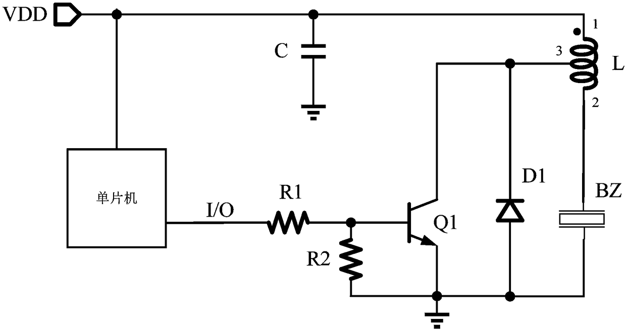
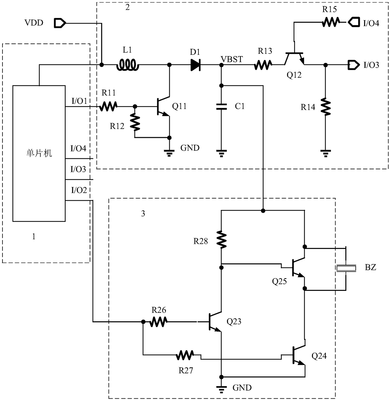
[0063] The drive circuit of the buzzer includes a control circuit module, a boost circuit module and a switch drive circuit module;
[0064] The first output end of the control circuit module is connected to the input end of the boost circuit module, the second output end of the control circuit module is connected to the first input end of the switch drive circuit module, The control circuit module is used to control the working state of the boost circuit module and the switch drive circuit module;
[0065] The power supply terminal of the boost circuit module is connected to the voltage source, the output terminal of the boost circuit module is connected to the second input terminal of the switch drive circuit module, and the boost circuit module is used to connect the v...
PUM
 Abstract
Description
Claims
Application Information