Stripping guiding device for orthopedic surgery

A guiding device and orthopedic surgery technology, applied in the field of medical devices, can solve the problems of inconvenience, no mention of guiding and winding, etc., and achieve the effects of improving strength, preventing damage and reducing thickness

Active Publication Date: 2018-12-18
李莉
View PDF7 Cites 0 Cited by
  • Summary
  • Abstract
  • Description
  • Claims
  • Application Information

AI Technical Summary

Problems solved by technology

Chinese patent CN207545067U discloses "a multi-functional handle for knee arthroscopy". The handle can play a certain protective role. The concave part is set to facilitate the drilling of the drill bit, and a convex mirror surface is arranged around the concave part to facilitate the operator's observation. , but the device does not mention how to solve the problem of inconvenient guidance and winding

Method used


Image

  • Stripping guiding device for orthopedic surgery
  • Stripping guiding device for orthopedic surgery
  • Stripping guiding device for orthopedic surgery

Examples


Embodiment 1

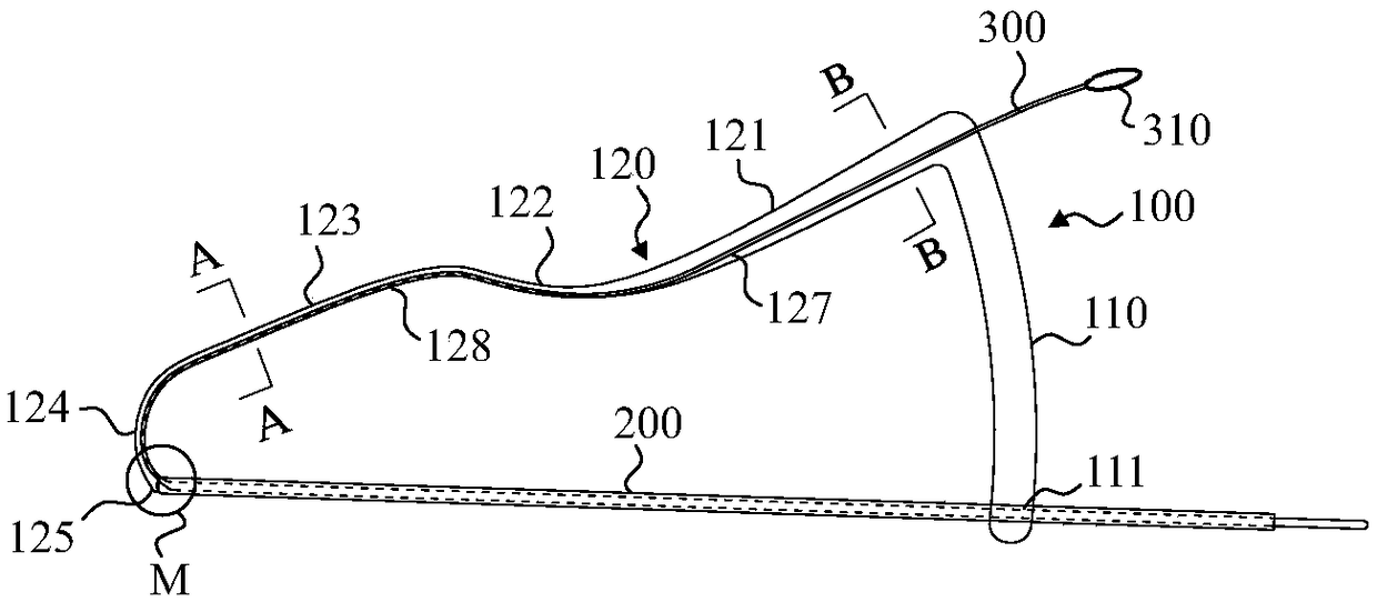
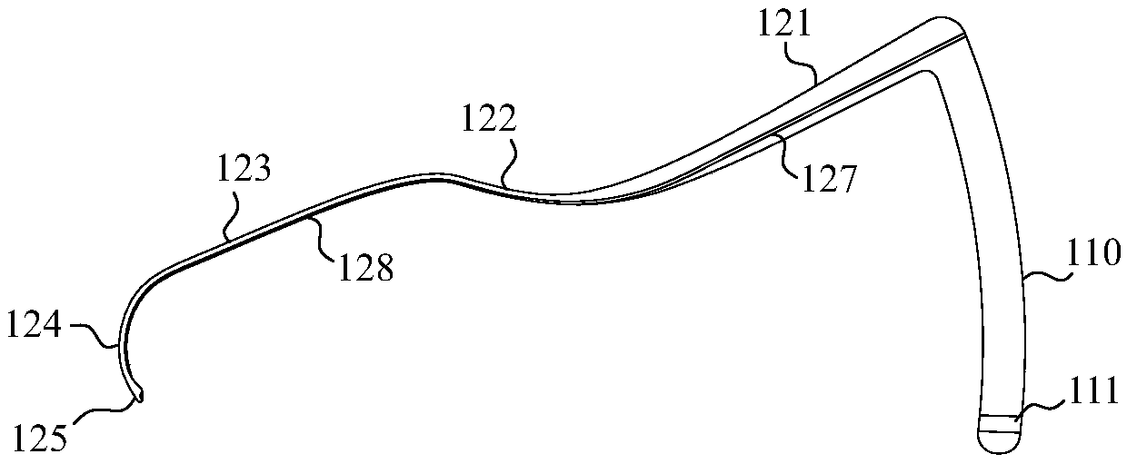
[0024] Such as figure 1 , figure 2 , Figure 5 As shown, a peeling guide device for orthopedic surgery includes a handle 100 made of titanium alloy material, a guide rod 200 and a guide wire 300 . The handle 100 includes a wide handle portion 110 and a guide portion 120 at an angle of 80-100° to each other. The wide handle portion 110 has a certain arc and is provided with a guide groove 111 for the guide rod 200 to pass through. The guide part 120 includes a first rod body 121 connected to the wide handle part 110, a first curved part 122 offset to the outside at a certain angle, a second rod body 123 connected to the first curved part 122, and a first rod body 123 bent inward by a certain arc. Two curved parts 124 , the arc of the second curved part 124 is 90°-120°, and the free end of the second curved part forms an enlarged part 125 .

[0025] The guide part 120 is provided with a perforation for the guide wire 300 to penetrate from the wide handle part 110 and pass ou...

Embodiment 2

[0027] Compared with Embodiment 1, this embodiment adopts the combination of perforation and passing groove to provide a passing channel for the guide wire 300 . Specifically, start with figure 1 , figure 2 , Figure 5 based on the combination image 3 , Figure 4 As shown, the thickness of the first rod body 121 is 8-15 mm, the thickness of the second rod body 123 and the second bending portion 124 are 4-6 mm, and the diameter of the guide rod 200 is 6-8 mm.

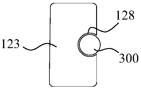
[0028] The first rod body 121 is provided with a perforation 127 for the guide wire 300 to pass through, and the inner surfaces of the first curved part 122, the second rod body 123 and the second curved part 124 form a passing groove 128 communicating with the perforating hole 127, and the passing groove 128 Form a limited fit with the guide wire 300 . This design can further reduce the thickness of the handle and reduce the damage to the stripped blood vessels, nerves, and muscle tissue. The grooves pass through...


PUM


Abstract

The invention discloses a stripping guiding device for an orthopedic surgery. The device comprises a handle, a guiding rod and a guiding wire; the handle comprises a wide handle part, a guiding part and a bending part, and the guiding part is provided with a penetrating hole and/or a penetrating groove used for the guiding wire to penetrate from the wide handle part out of a free end; a blunt endis arranged at the front end of the guiding rod and is in threaded connection with the free end of the guiding part; the handle is provided with a guiding groove used for the guiding rod to penetratethrough and cooperative with a fixed groove. The device is applicable to the stripping of muscle tissue, nerve and blood vessels and the penetrating and guiding of the guiding wire and a lead line tobundle or fix bone blocks and ligaments. The bending part of the device can effectively prevent that in the stripping process, the muscle tissue is injured, the thickness of the handle is reduced as far as possible on the basis of ensuring the guiding wire to normally penetrate, and especially the guiding groove formed in the inner surface of the handle has the reinforcing rib effect to improve the strength of a stress point of the handle.

Description

technical field [0001] The invention relates to a surgical auxiliary device in the field of medical devices, in particular to a stripping guide device for orthopedic surgery. Background technique [0002] In orthopedic surgery, it is often applied to the situation where it is necessary to bind the bone with a needle guide cable or to fix the insertion point of the ligament and tendon, which plays an important role in maintaining the mechanical stability of the bone and the motor function of the tendon. Some of the current guiding and winding methods are simple and rude, which cause great damage to the periosteum tissue and lack protection measures for important blood vessel and nerve tissues. Existing auxiliary devices lack separation and protection for surgically separated muscles, nerves, and vascular tissues, which can easily cause damage; some threading and threading devices are three-dimensional stent structures, which are too complicated and heavy, which is not conduci...

Claims


Application Information

Patent Timeline
Patent Type & Authority Applications(China)
IPC IPC(8): A61B17/32A61B17/82A61B90/11
CPCA61B17/320016A61B17/82A61B2017/564A61B90/11
Inventor 李颖周万宸李克冉
Owner 李莉
Why Eureka
Try Eureka