
A method for cutting aircraft engine blades

An aircraft engine and cutting method technology, applied in electric processing equipment, metal processing equipment, manufacturing tools, etc., can solve problems such as blade failure, hidden danger of engine safe use, and surface aluminized layer damage.

Inactive Publication Date: 2021-02-09
GUIZHOU KAIYANG AERO ENGINE
View PDF8 Cites 0 Cited by
  • Summary
  • Abstract
  • Description
  • Claims
  • Application Information

AI Technical Summary

Problems solved by technology

[0002] During the use of the low-pressure turbine guide of the engine, due to the appearance of local high-temperature zones on the surface of the blade, the aluminized layer on the surface will be damaged, resulting in thermal ablation points, which will then be derived into cracks or holes that gradually extend from the outside to the inside, resulting in The ablation area gradually expands, resulting in blade failure, which brings hidden dangers to the safe use of the engine
In order to remove the ablated faulty blades, the faulty low-pressure turbine guide blades on the engine are safely and reliably cut out by means of electric spark cutting, laying technical preparations for the subsequent replacement of good blades, and solving the problem of engine low-pressure turbine guide blades. The blade failure of the engine provides good economic benefits and technical support, but simply cutting the blades of the low-pressure turbine guide of the engine will easily cause the instability of the blades, resulting in failure of the low-pressure turbine guide of the engine after replacing the blades

Method used


Image

  • A method for cutting aircraft engine blades

Examples


Embodiment

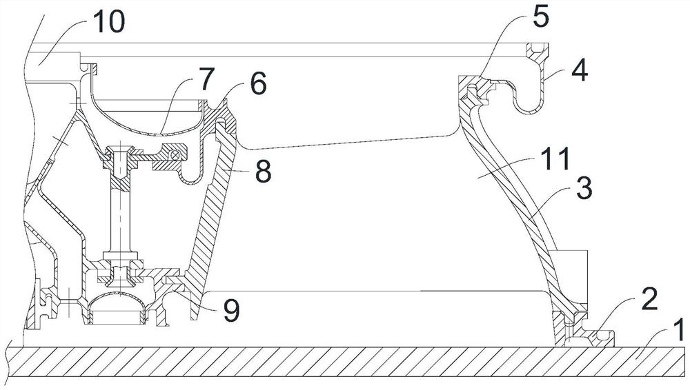
[0040] This cutting method is EDM cutting. The low-pressure turbine guider 10 of the engine is placed horizontally on the EDM equipment platform 1 with the intake side facing upward. The blade is connected to the positive stage of the pulse power supply, and the pulse power supply is loaded between the positive and negative electrodes. When an electric pulse is formed, a spark discharge will be generated between the tip of the copper sheet and the blade, and the central temperature in the discharge channel will reach thousands of degrees instantaneously. The high temperature melts the local metal of the blade to form a thinner slit to achieve the purpose of cutting;

[0041] The specific cutting steps are as follows:

[0042] Step 1: Cut the left and right ends of the lower edge plate 8 of the blade perpendicular to the EDM equipment platform 1 in a direction perpendicular to the upper surface of the EDM equipment platform 1, the distance between the cutting edge and the brazi...


PUM


Abstract

The invention relates to a cutting method of aircraft engine blades. The cutting method is electrical discharge machining cutting, and the engine low-pressure turbine guider is placed horizontally on the electric discharge equipment platform with the intake side facing upwards, including the following cutting steps: The left and right ends of the edge plate are cut along the horizontal direction; the left and right ends of the upper edge plate of the blade are cut along the horizontal direction; the left and right ends of the first fixing ring are cut vertically downward; the left end of the bellows and right end; cut straight down left and right ends of first mounting edge; cut straight down second retaining ring end; left and right end of second mounting edge Cut straight down. Cutting the blade of the low-pressure turbine guider of the aircraft engine by the method can ensure the stability of the aircraft engine, so that the replaced blade matches the original blade and maintains the same stability.

Description

technical field [0001] The invention relates to the technical field of maintenance of aircraft engine blades, in particular to a cutting method for aircraft engine blades. Background technique [0002] During the use of the low-pressure turbine guide of the engine, due to the appearance of local high-temperature zones on the surface of the blade, the aluminized layer on the surface will be damaged, resulting in thermal ablation points, which will then be derived into cracks or holes that gradually extend from the outside to the inside, resulting in The ablation area gradually expands, forming a blade failure, which brings hidden dangers to the safe use of the engine. In order to remove the ablated faulty blades, the faulty low-pressure turbine guide blades on the engine are safely and reliably cut out by means of electric spark cutting, laying technical preparations for the subsequent replacement of good blades, and solving the problem of engine low-pressure turbine guide bl...

Claims


Application Information

Patent Timeline
Patent Type & Authority Patents(China)
IPC IPC(8): B23H1/00B23H11/00
CPCB23H1/00B23H11/003
Inventor 陈犇张国俊周正刁爱军苏静尹丽萍
Owner GUIZHOU KAIYANG AERO ENGINE
Learn More