Local dry underwater laser welding system and method for simulating deep water environment

A local dry method, welding system technology, applied in laser welding equipment, welding equipment, metal processing equipment, etc., can solve problems that cannot be used to study laser welding process engineering

Active Publication Date: 2018-12-18
HUAZHONG UNIV OF SCI & TECH
View PDF5 Cites 5 Cited by
  • Summary
  • Abstract
  • Description
  • Claims
  • Application Information

AI Technical Summary

Problems solved by technology

Therefore, the current shallow water simulation device cannot be used to study laser welding process engineering in deep water environment.

Method used


Image

  • Local dry underwater laser welding system and method for simulating deep water environment
  • Local dry underwater laser welding system and method for simulating deep water environment
  • Local dry underwater laser welding system and method for simulating deep water environment

Examples


Embodiment Construction

[0037] In order to make the object, technical solution and advantages of the present invention clearer, the present invention will be further described in detail below in conjunction with the accompanying drawings and embodiments. It should be understood that the specific embodiments described here are only used to explain the present invention, not to limit the present invention. In addition, the technical features involved in the various embodiments of the present invention described below can be combined with each other as long as they do not constitute a conflict with each other.

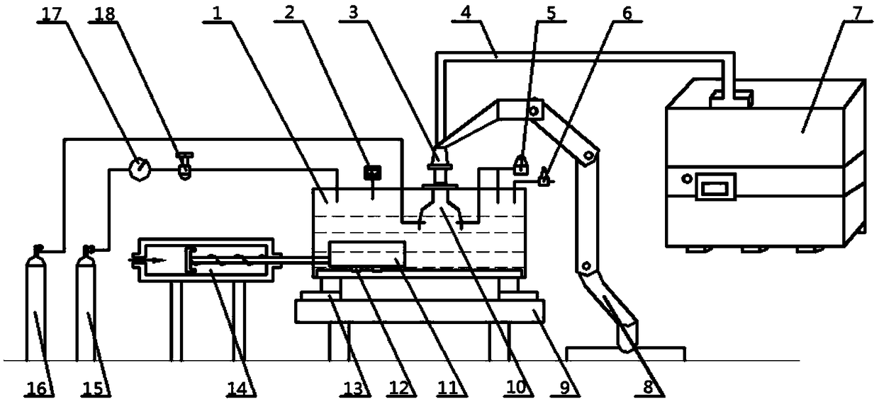
[0038] figure 1 It is a schematic diagram of the overall structure involved in the use of a partial dry underwater laser welding system that simulates a deep water environment in an embodiment of the present invention, as shown in figure 1 As shown, a local dry underwater laser welding system simulating a deep water environment includes: a fully enclosed water tank 1, a pressure reducing valve ...


PUM


Abstract

Disclosed is a local dry underwater laser welding system for simulating a deep water environment, comprising a welding system, a high-pressure gas control system, a fully enclosed water tank (1), anda movable welding table (11) arranged at the bottom of the fully enclosed water tank (1). The fully-enclosed water tank (1) comprises an upper end cover plate (25) of a tank body, a lower end cover plate (32) of the tank body, and a side plate. The high-pressure gas control system together with the fully enclosed water tank (1) forms a high-pressure environment and a stable local drying space, thereby realizing high-pressure underwater laser welding of a part (24) to be welded fixed on a belt of the movable welding table (11). The invention also discloses a local dry underwater laser welding method for simulating the deep water environment, which is convenient to operate and can safely and stably obtain a high quality weld through simulating a real deep water environment.

Description

technical field [0001] The invention belongs to the technical field of complete sets of underwater laser welding equipment, and more specifically relates to a partial dry underwater laser welding system and method for simulating a deep-water environment. Background technique [0002] At present, there is no suitable method for correcting the deformation of side beams in the field of rail vehicle maintenance. The traditional process uses thermal correction, that is, heating the deformed side beams and then correcting the side beams whose hardness has decreased. With the continuous deepening of human understanding of the ocean, the rich marine resources attract humans to deeper and wider ocean areas, and more and more marine infrastructures have been built. The establishment and maintenance of offshore infrastructure is inseparable from the progress and perfection of underwater welding technology. As a new type of automatic production process, underwater laser welding has th...

Claims


Application Information

Patent Timeline
Patent Type & Authority Applications(China)
IPC IPC(8): B23K26/21B23K26/12B23K26/122B23K26/70
CPCB23K26/1224B23K26/123B23K26/127B23K26/21B23K26/702
Inventor 庞盛永李权洪黄安国罗曼乐兰胡仁志
Owner HUAZHONG UNIV OF SCI & TECH
Why Eureka
Try Eureka