Novel burr remover

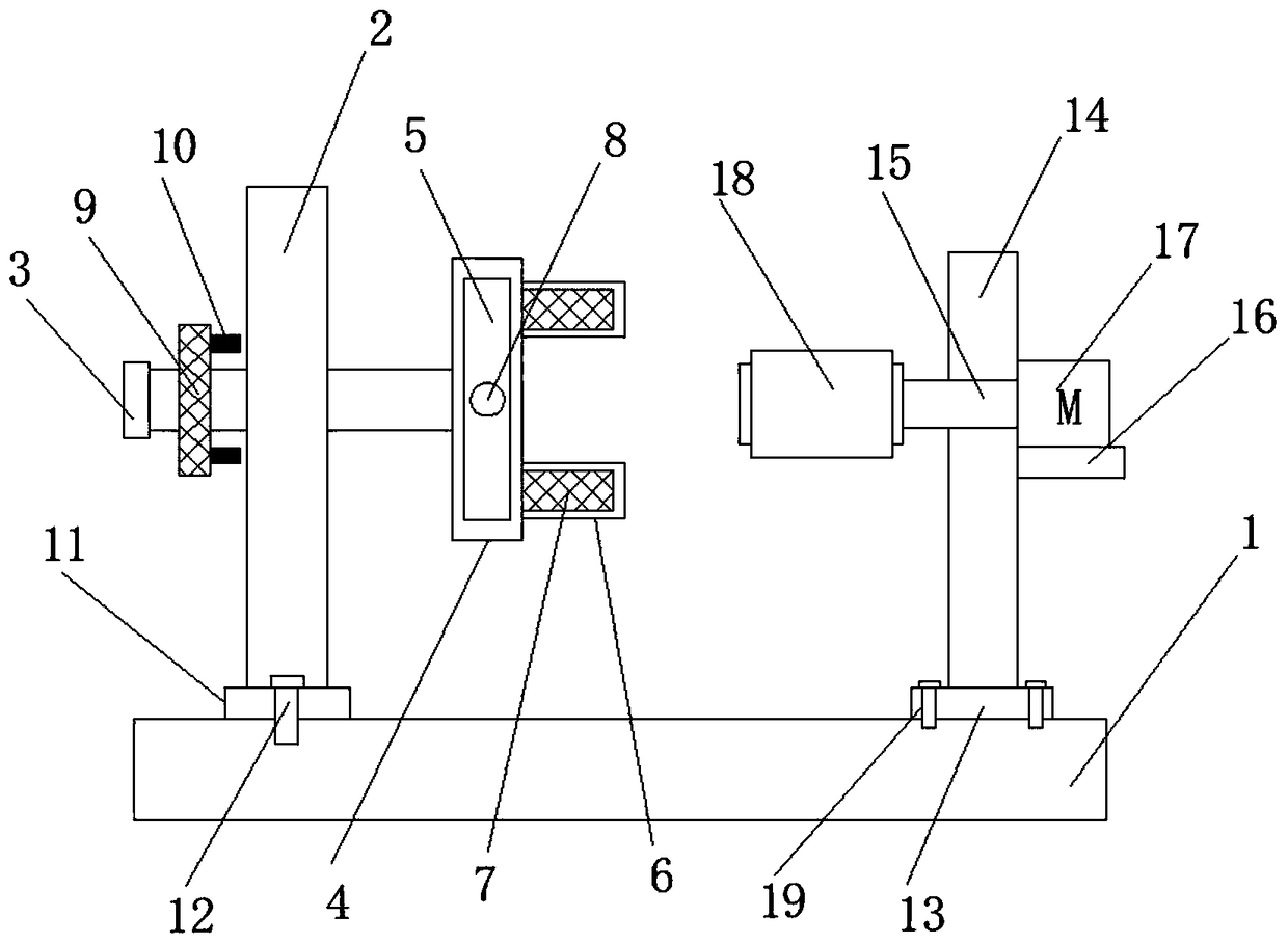
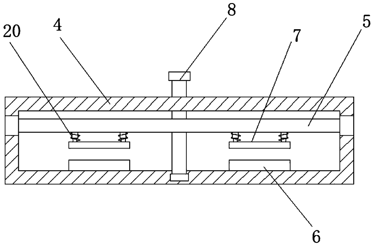
A new type of burr removal technology, which is applied to grinding racks, machine tools suitable for grinding workpiece edges, grinding machines, etc., can solve the problems of low workpiece processing efficiency, lack of steering structure for workpiece clamping, etc., to reduce processing costs, Convenient and fast clamping, simplifying the effect of the clamping device

Inactive Publication Date: 2018-12-18
谢兴艺
View PDF0 Cites 0 Cited by
  • Summary
  • Abstract
  • Description
  • Claims
  • Application Information

AI Technical Summary

Problems solved by technology

[0003] However, the existing deburring device lacks a steering structure for clamping the workpiece, so that when processing other sides of the workpiece, it is necessary to disassemble the workpiece and re-clamp it for reprocessing, and the processing efficiency of the workpiece is low

Method used


Image

  • Novel burr remover
  • Novel burr remover

Examples


Embodiment Construction

[0019] The following will clearly and completely describe the technical solutions in the embodiments of the present invention with reference to the accompanying drawings in the embodiments of the present invention. Obviously, the described embodiments are only some, not all, embodiments of the present invention.

[0020] In describing the present invention, it should be understood that the terms "upper", "lower", "front", "rear", "left", "right", "top", "bottom", "inner", " The orientation or positional relationship indicated by "outside", etc. is based on the orientation or positional relationship shown in the drawings, and is only for the convenience of describing the present invention and simplifying the description, rather than indicating or implying that the referred device or element must have a specific orientation, so as to Specific orientation configurations and operations, therefore, are not to be construed as limitations on the invention.

[0021] refer to Figure ...


PUM


Abstract

The invention discloses a novel burr remover which comprises a baseplate, wherein a first sliding slot is arranged in the horizontal direction of the upper side of the baseplate; a first limiting plate which is slidably connected with the first sliding slot is arranged in the first sliding slot; a first supporting plate which is fixedly connected with the first limiting plate is arranged on the upper side of the first limiting plate; a rotating rod which is rotationally connected with the first supporting plate is arranged in the horizontal direction of the first supporting plate in an inserting manner; a clamping device is arranged at the right end of the rotating rod; a limiting device which is slidably connected with the rotating rod is connected onto the rotating rod in a sleeving manner; a second sliding slot is arranged on the upper side of the baseplate; the first sliding slot is perpendicular to the second sliding slot; a second limiting plate which is slidably connected with the second sliding slot is arranged in the second sliding slot; and a second supporting plate which is fixedly connected with the second limiting plate is arranged on the upper side of the second limiting plate. The novel burr remover disclosed by the invention has the advantages that a steering device is added to the clamping device for a workpiece, so that the workpiece can be driven to rotate aslong as the steering device is rotated during the workpiece machining process, the clamping of the workpiece is no longer needed, and the workpiece machining efficiency can be improved.

Description

technical field [0001] The invention relates to the technical field of workpiece processing, in particular to a novel deburring machine. Background technique [0002] Some of the burrs on mechanical parts are caused by plastic deformation during cutting; some are flashes from casting, die forging, etc., and some are residues from welding extrusion. With the improvement of industrialization and automation, in the field of mechanical processing, especially in the fields of aviation, aerospace, and instrumentation, the requirements for the precision of mechanical parts manufacturing and the miniaturization of mechanism design, the harmfulness of burrs is particularly obvious, which gradually arouses people's attention. General attention. [0003] However, the existing deburring device lacks a steering structure for clamping the workpiece, so that when other sides of the workpiece are processed, the workpiece needs to be disassembled and re-clamped for reprocessing, and the pro...

Claims


Application Information

Patent Timeline
Patent Type & Authority Applications(China)
IPC IPC(8): B24B9/02B24B41/06B24B41/02
CPCB24B9/02B24B41/02B24B41/06
Inventor 谢兴艺
Owner 谢兴艺
Why Eureka
Try Eureka