3D printing equipment

A 3D printing and equipment technology, applied in the field of 3D printing, can solve the problems of reducing the workbench area, prolonging the printing time, increasing the equipment cost, etc., and achieving the effect of reducing the size of the equipment, reducing the volume and reducing the equipment cost.

Pending Publication Date: 2018-12-18
GUANGZHOU OGGI3D ELECTROMECHANICAL
View PDF0 Cites 2 Cited by
  • Summary
  • Abstract
  • Description
  • Claims
  • Application Information

AI Technical Summary

Problems solved by technology

[0003] 1. The length of the discharge channel of the discharge trough is equal to the length of the discharge channel of the scraper and is equal to the width of the workbench. The printing materials such as sand in the discharge channel flow out from the discharge channel and fall through the discharge channel of the scraper. When entering the workbench, due to the fluidity of the sand, a part of the sand will gather on both sides of the scraper and overflow the workbench when the scraper moves; in order to avoid the overflowing sand from affecting the operation and to facilitate sand recycling, the usual solution The solution is to set up a recovery tank around the workbench, so that the sand overflowing the workbench falls into the recovery tank; this method can solve the problem of sand overflow, but when the size of the 3D printing equipment remains unchanged, adding a recovery tank will reduce the the area of ​​the workbench;
[0004] 2. When the printing material is spread on the workbench, the two layers of printing materials usually need to be bonded with glue. In order to make the printed product structure firm, a layer of printing material is usually spread and a layer of glue is sprayed; usually the printing material is sprayed with glue Finally, the glue needs to solidify before laying down a layer of printing materials. When the working environment temperature is low, it usually needs to wait, which prolongs the printing time; in addition, some printing materials need to be heated before spraying glue to eliminate their internal stress. , but if a heating hood is installed above the working group, the whole working group will ensure a higher temperature, but the heating of the printing materials is not ideal;
[0005] 3. When the feeding mechanism adopts upper end feeding, in order to make the feeding of the feeding chute uniform, the length of the outlet of the feeding chute is usually adapted to the length of the feeding port of the feeding chute and cannot be longer than the bottom of the feeding chute. The length of the feeding channel is short; when the size of the 3D printing equipment is small or the size of the product to be printed is small, the smaller feeding channel can be fed in this way; but when the size of the 3D printing equipment is large, And when it is necessary to print larger-sized products, this feeding method increases the volume of the equipment, making the equipment occupy a large space. At the same time, due to the large size of the feeding tank, it is not necessary to increase the cost input and increase the equipment cost; and divide During the feeding process, the rotation of the distribution roller will generate centrifugal force, which will make the sand that was originally uniform in the distribution roller gather to both sides, making the feeding uneven

Method used


Image

  • 3D printing equipment
  • 3D printing equipment
  • 3D printing equipment

Examples


Embodiment Construction

[0061] The present invention will be further described below in conjunction with the accompanying drawings and preferred embodiments.

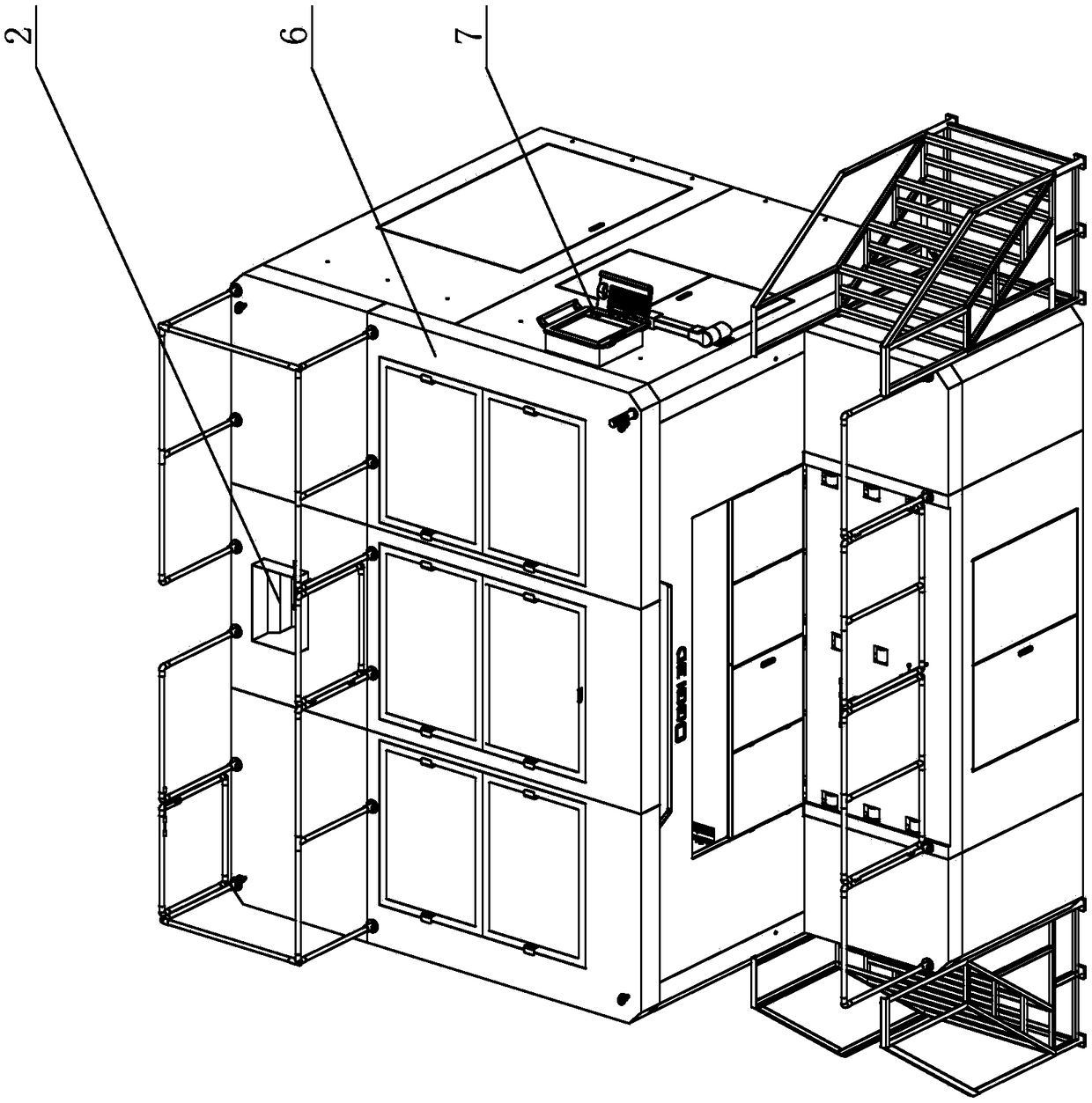
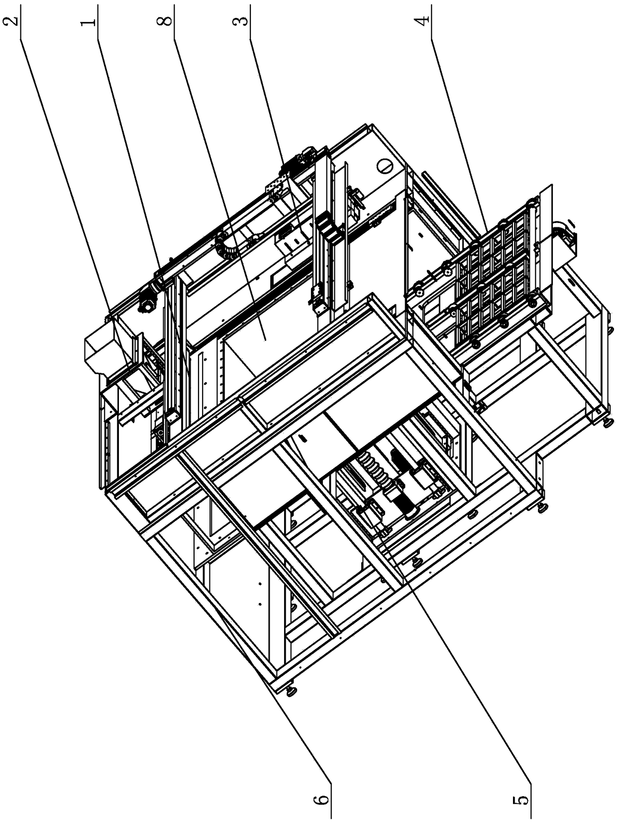
[0062] Such as figure 1 , figure 2 As shown, a kind of 3D printing equipment, described 3D printing equipment comprises frame 6, is located on the control system 7 on frame 6, is located on the feeding mechanism 2 that is electrically connected with control system 7 on frame 6, unloading Mechanism 1, glue spraying mechanism 3, lifting mechanism 5, conveying mechanism 4 and working cylinder 8 located on the conveying mechanism 4; said working cylinder 8 can be transported to the center of frame 6 under the action of conveying mechanism 4 and Lifting or descending under the action of the lifting mechanism 5; the unloading mechanism 1 is arranged on the rear side of the frame 6 and can reciprocate on both sides of the front and rear sides of the working cylinder 8 under the action of the control system 7 and lay the printing material on the On...


PUM


Abstract

The invention discloses 3D printing equipment. The 3D printing equipment comprises a rack, a feeding mechanism, a discharging mechanism, a glue spraying mechanism, a lifting mechanism, a conveying mechanism and a working cylinder, wherein the feeding mechanism, the discharging mechanism, the glue spraying mechanism, the lifting mechanism and the conveying mechanism are arranged on the rack and electrically connected with a control system, and the working cylinder is arranged on the conveying mechanism. The feeding mechanism can communicate with the discharging mechanism and can supply printingmaterials to the discharging mechanism under the effect of the control system. The glue spraying mechanism can spray glue onto the printing materials under the effect of the control system. Comparedwith the prior art, the 3D printing equipment has the advantages that no recycling trough needs to be reserved around the working cylinder so that larger parts can be printed; heating assemblies electrically connected with the control system are arranged on the front side and the rear side of a spraying cover so that the printing materials sprayed with the glue can be heated by the heating assembly at the rear end in the moving direction to accelerate solidification, printing materials to be sprayed with glue can be heated in advance through the heating assembly at the front end in the movingdirection, and accordingly, internal stress of the printing materials is eliminated to bond the glue and the printing materials.

Description

technical field [0001] The invention relates to the technical field of 3D printing, in particular to a 3D printing device. Background technique [0002] In the field of 3D printing technology, existing printing equipment has the following problems: [0003] 1. The length of the discharge channel of the discharge trough is equal to the length of the discharge channel of the scraper and is equal to the width of the workbench. The printing materials such as sand in the discharge channel flow out from the discharge channel and fall through the discharge channel of the scraper. When entering the workbench, due to the fluidity of the sand, a part of the sand will gather on both sides of the scraper and overflow the workbench when the scraper moves; in order to avoid the overflowing sand from affecting the operation and to facilitate sand recycling, the usual solution The solution is to set up a recovery tank around the workbench, so that the sand overflowing the workbench falls i...

Claims


Application Information

Patent Timeline
IPC IPC(8): B28B1/00B33Y30/00
CPCB28B1/001B33Y30/00
Inventor 王晓斌曾源唐健杰凌虓威陈国清
Owner GUANGZHOU OGGI3D ELECTROMECHANICAL
Why Eureka
Try Eureka