Locomotive rail-coated nozzle fixing device

A technology for coating nozzles and fixing devices, which is applied to the equipment fixed on the vehicle, transportation and packaging, railway car body parts, etc. It can solve the problem of excessive friction at the contact position between the wheel and the curved rail, and the difficulty in adjusting the position accuracy of the nozzle position , affect the service life of rails and wheels, and achieve the effect of convenient and reliable positioning adjustment, meeting precision requirements, and compact structure

Pending Publication Date: 2018-12-18
济南三新铁路润滑材料有限公司
View PDF8 Cites 0 Cited by
  • Summary
  • Abstract
  • Description
  • Claims
  • Application Information

AI Technical Summary

Problems solved by technology

Due to the frequently changing characteristics of the workplace, it needs to be frequently installed and removed from the rear compartment of the passenger train. The position of the nozzle needs to be adjusted in advance before work. In the prior art, the adjustment of the position of the nozzle is more complicated and the position accuracy is not easy to adjust. Not only The workload of the operator is heavy, and it is also prone to inaccurate spraying positions, resulting in that the lubricant cannot be sprayed to the required position accurately. Since there is no detection equipment to observe and detect changes in the position of the nozzle in time, when the nozzle cannot be accurately aligned with the required When the rail is sprayed, it will cause excessive friction and wear at the contact position between the wheel and the curved rail, which will affect the service life of the rail and the wheel, and it is prone to failures in driving safety and operation
[0003] In addition, the nozzle devices used in the prior art for coating the tail of passenger trains are not suitable for the lubrication requirements of freight lines.

Method used


Image

  • Locomotive rail-coated nozzle fixing device
  • Locomotive rail-coated nozzle fixing device
  • Locomotive rail-coated nozzle fixing device

Examples


Embodiment Construction

[0034] In order to enable those skilled in the art to better understand the technical solutions in the present invention, the technical solutions in the embodiments of the present invention will be clearly and completely described below in conjunction with the drawings in the embodiments of the present invention. Obviously, the described The embodiments are only some of the embodiments of the present invention, not all of them.

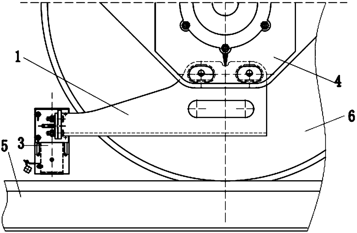
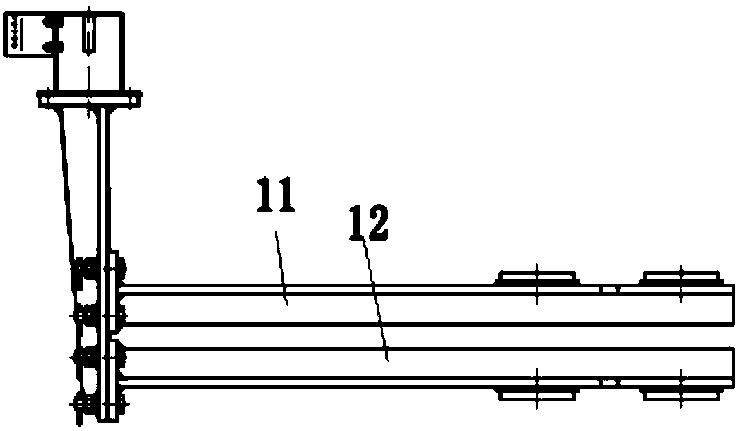
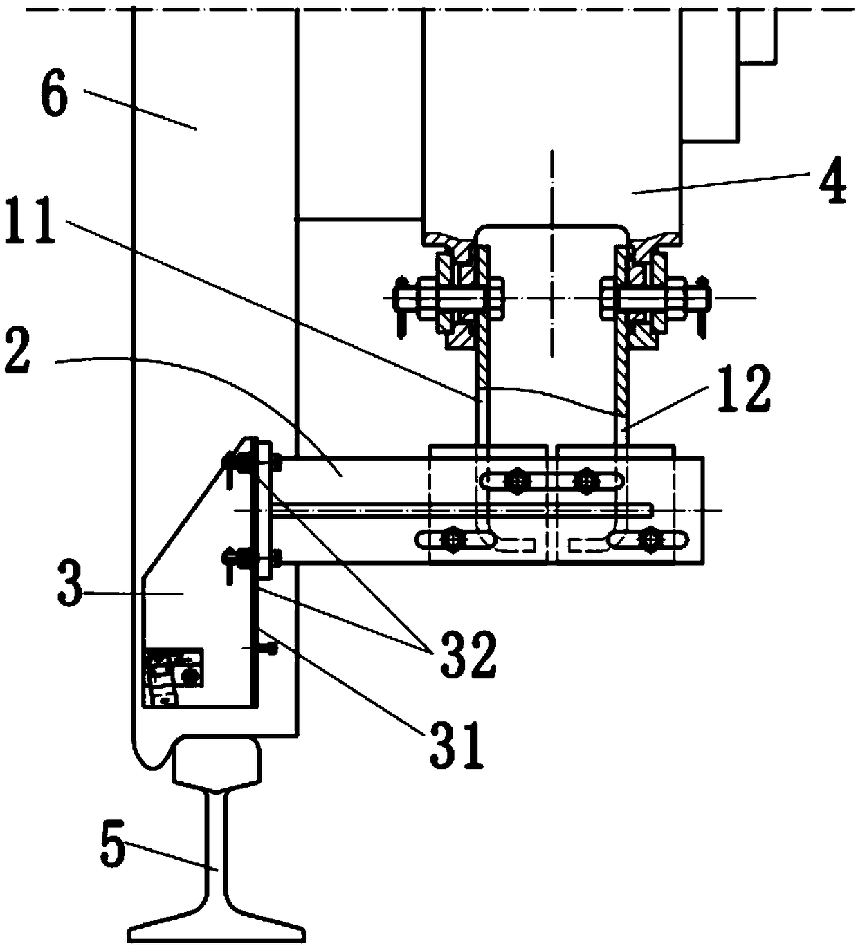
[0035] Such as Figure 1-9 As shown, a rail coating nozzle fixing device for a locomotive includes a left and right support assembly 1, a lateral support assembly 2, and a nozzle box 3. The left and right support assembly 1 includes a left support seat 11 and a right support seat 12. The left support The upper part of the seat 11 is connected with the inner side of the left side of the locomotive wheel bearing body 4 through a combination of bolts and nuts; the upper part of the right support seat 12 is connected with the inner side of the right side ...


PUM


Abstract

The invention discloses a locomotive rail coat nozzle fixing device which includes a left and right support combination, transverse support combindation, a nozzle box, the left and right support assemblies comprising a left support seat, Right support seat, An upper part of that left support seat is connected with an inner side of a left side of a locomotive wheel bear body through a bolt-nut combination, An upper part of that right support seat is connected with an inner side of a right side of a locomotive wheel bear body through a bolt-nut combination, a lower part of the left support seatand a lower part of the right support seat are respectively connected with one end of a transverse support combination, and the other end of the transverse support combination is connected with a spray head box. The upper part of the right support seat is connected with an inner side of the right side of the locomotive wheel bearing body through a bolt-nut combination. The invention can conveniently adjust the horizontal position and the vertical position of the spray head, greatly reduces the workload of the coating operator, the positioning adjustment of the spray head is convenient and reliable, ensures that the nozzle position and the rail coating position are at the best matching position, so that the position of the lubricating oil coated on the rail is more accurate, and the consumption of the lubricating oil is less.

Description

technical field [0001] The invention relates to the technical field of dry lubricating coating equipment for curved rails, in particular to a rail coating nozzle fixing device for locomotives. Background technique [0002] The vehicle-mounted curved rail dry lubricating coating device in the prior art is usually used as a spray head device for coating the tail of a passenger train. Due to the frequently changing characteristics of the workplace, it needs to be frequently installed and removed from the rear compartment of the passenger train. The position of the nozzle needs to be adjusted in advance before work. In the prior art, the adjustment of the position of the nozzle is more complicated and the position accuracy is not easy to adjust. Not only The workload of the operator is heavy, and it is also prone to inaccurate spraying positions, resulting in that the lubricant cannot be sprayed to the required position accurately. Since there is no detection equipment to observ...

Claims


Application Information

Patent Timeline
Patent Type & Authority Applications(China)
IPC IPC(8): B61K5/02
CPCB61K5/02
Inventor 曹传东马进国曹爱提赵萍杨霄袁飞李荣辉张祥东李进
Owner 济南三新铁路润滑材料有限公司
Why Eureka
Try Eureka