Short pitch film cutting machine

A cutting machine and film technology, applied in thin material processing, winding strips, sending objects, etc., can solve the problems of different film lengths, film wrinkles, low efficiency, etc., to achieve simple and convenient clamping operation and reduce wrinkles possibility, reasonable effect of structural design

Inactive Publication Date: 2018-12-18
HONGCHENG SCI & TECH LTD
View PDF5 Cites 10 Cited by
  • Summary
  • Abstract
  • Description
  • Claims
  • Application Information

AI Technical Summary

Problems solved by technology

[0003] The application of the film needs to be cut into sections of equal length and rolled into balls for later use. The film cutting in the prior art is all done manually, that is, a rolling support is set, and then a crank is set on one side of the rolling support. Manually shake the handle and calculate the number of rotations, and then cut the film manually. Using this traditional manual operation is inefficient and has errors, resulting in different lengths of the cut film, affecting the normal use of the user, and When the film is cut into small rolls from a large roll of film, the large roll of film will gradually become smaller. If the stretching speed is the same, the film will easily wrinkle, which will affect the cutting and use of the film. Therefore, We propose a short pitch film cutter

Method used


Image

  • Short pitch film cutting machine
  • Short pitch film cutting machine
  • Short pitch film cutting machine

Examples


Embodiment Construction

[0024] The following will clearly and completely describe the technical solutions in the embodiments of the present invention with reference to the accompanying drawings in the embodiments of the present invention. Obviously, the described embodiments are only some, not all, embodiments of the present invention. Based on the embodiments of the present invention, all other embodiments obtained by persons of ordinary skill in the art without creative efforts fall within the protection scope of the present invention.

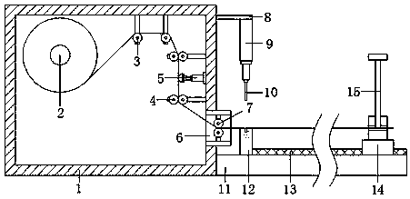
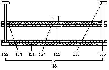
[0025] see Figure 1-3 As shown, this embodiment is a short-distance film cutting machine, including a feeding box 1, a feeding roller 2 is arranged on the left side of the inner cavity of the feeding box 1, and the left and right sides of the inner cavity of the feeding box 1 are symmetrical. A guide roller 3 is provided, and the left guide roller 3 is located on the right side of the delivery roller 2, and the upper and lower sides of the right side wall of the i...


PUM


Abstract

The invention discloses a short pitch film cutting machine. The short pitch film cutting machine comprises a material conveying box; a material conveying roll is arranged on the left side of an innercavity of the material conveying box; material guide rolls are symmetrically arranged on the left side and the right side of the top of the inner cavity of the material conveying box; an adjustment and material guide pair roll is arranged at the right side wall of the inner cavity of the material conveying box; an electric telescopic rod is arranged at the right side wall of the inner cavity of the material conveying box; a discharge port is formed at the bottom of the right side wall of the material conveying box; a parallel material guide pair roll is arranged at an inner cavity of the discharge port; a supporting frame is arranged at the top of the right side wall of the material conveying box; a pneumatic telescopic rod is arranged at the bottom of the supporting frame; a cutting knifeis arranged at the bottom of the pneumatic telescopic rod; a supporting base is arranged at the bottom of the right side wall of the material conveying box; a cutting table and a sliding rail are arranged at the top of the supporting base; the top of the sliding rail is connected with an electric sliding block in a sliding manner; and a film fixing mechanism is arranged at the top of the electricsliding block. The short pitch film cutting machine is reasonable in structural design, the probability of folding during film cutting can be reduced, an error during cutting is lowered, and adjustments can be made according to the requirement on the cut length.

Description

technical field [0001] The invention relates to the technical field of cutting machines, in particular to a short-distance film cutting machine. Background technique [0002] The automatic cutting machine is used for the division and cutting of sheets in all walks of life. It does not need any molds; it is controlled by the system software, and then directly cuts the product, as long as the corresponding parameters are set on the operating platform, The computer transmits corresponding instructions to the cutting machine; the cutting machine quickly cuts according to the accepted design drawings, with high automation procedures and simple operation. It is the cutting equipment used in many industries, and there are many kinds of cutting machines, which are widely used in various fields. [0003] The application of the film needs to be cut into sections of equal length and rolled into balls for later use. The film cutting in the prior art is all done manually, that is, a rol...

Claims


Application Information

Patent Timeline
Patent Type & Authority Applications(China)
IPC IPC(8): B65H16/00B65H43/08B65H35/06B65H23/26B65H23/188B65H23/34
CPCB65H16/00B65H23/1888B65H23/26B65H23/34B65H35/06B65H43/08B65H2701/1133B65H2701/1752
Inventor 郭宏兵程春良程永胜郭澍
Owner HONGCHENG SCI & TECH LTD
Why Eureka
Try Eureka