Integral water stopping system and manufacturing method thereof

A production method and integrated technology, applied in water conservancy projects, underwater structures, artificial islands, etc., can solve the problems of long time and slow progress in the construction of waterstops, and achieve shortened construction progress, reduced time consumption, and convenient installation. Effect

Active Publication Date: 2018-12-18
广东蕉岭建筑工程集团有限公司
View PDF5 Cites 2 Cited by
  • Summary
  • Abstract
  • Description
  • Claims
  • Application Information

AI Technical Summary

Problems solved by technology

[0005] The present invention aims to provide a manufacturing method of an integral water stop system to solve

Method used


Image

  • Integral water stopping system and manufacturing method thereof
  • Integral water stopping system and manufacturing method thereof
  • Integral water stopping system and manufacturing method thereof

Examples


Embodiment 1

[0039]The utility model relates to an integral water-stop system, which is used for water-stop at the post-pouring belt, and is easy to install and can speed up the construction progress.

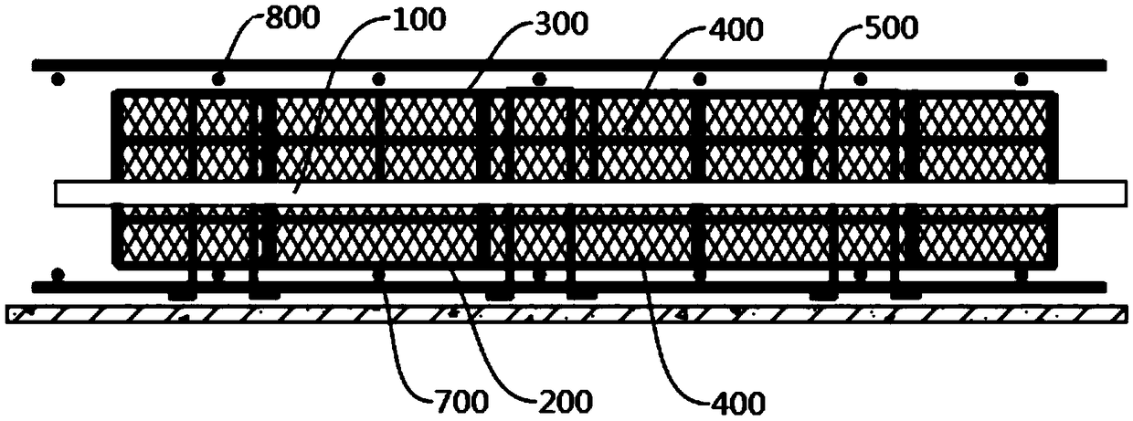
[0040] Please refer to the attached Figure 4 And attached Figure 5 , The integral water stop system includes a water stop strip composed of a steel frame, a water stop plate 100 and a steel wire mesh 400 .

[0041] Please refer to the attached Figure 6 , the overall steel frame is rectangular, and the two ends of the steel bars of the steel frame are bent back to form rounded corners.

[0042] Please refer to the attached Figure 6 , the steel wire mesh 400 is arranged on the steel bar skeleton, and is used as a formwork for pouring cast-in-place components. The density of the steel wire mesh 400 is based on the fact that the coarse aggregate of concrete corresponding to the cast-in-place component cannot pass through.

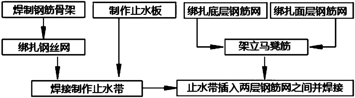
[0043] Refer to attached figure 1 As shown, the manufacturing ...

Embodiment 2

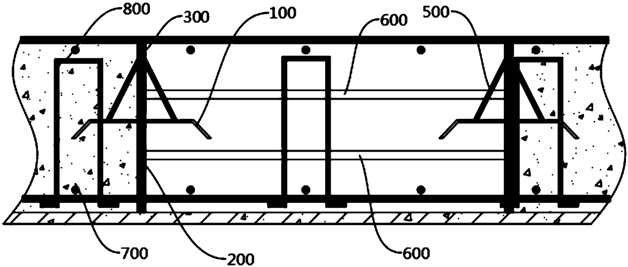
[0062] On the basis of embodiment 1, with reference to the attached Figure 7 As shown, in order to strengthen the anti-seepage effect, the post-casting belt of the present invention is set as follows:

[0063] The steel skeleton is staggered, the steel skeleton connected to the bottom steel mesh 700 is close to the post-cast belt, and the steel skeleton connected to the surface layer steel mesh 800 is far away from the post-cast belt, so that the end face of the cast-in-place component is stepped, and the post-cast belt is close to the surface layer It is wide at the bottom and narrow near the bottom layer. Even if a cold joint is formed between the cast-in-place component and the post-casting belt, the path of the cold seam from the bottom layer to the outer layer is curved and does not directly lead to the bottom layer, so it can further prevent water seepage from the surface layer. .

[0064] In order to further enhance the anti-seepage effect, the number of water stop bo...


PUM

PropertyMeasurementUnit
Bending angleaaaaaaaaaa

Abstract

The invention relates to the field of expansion joint post-cast strip water stopping systems, in particular to an integral water stopping system and a manufacturing method thereof. The integral waterstopping system is used for being arranged at the position of a post-cast strip to achieve a water stopping effect. The manufacturing method of the water stopping system mainly includes the steps thatrectangular reinforcement frameworks are manufactured; the two reinforcement frameworks are welded to the two faces of a water stopping plate, the water stopping plate and the reinforcement frameworks are inserted between a bottom-layer reinforcement net and a face-layer reinforcement net, the reinforcement frameworks on the two faces of the water stopping plate are fixedly connected with the bottom-layer reinforcement net and the face-layer reinforcement net, and the length of the water stopping plate is larger than or equal to the lengths of the reinforcement frameworks. The two steps of manufacturing a water stopping belt and manufacturing structural reinforcements can be carried out simultaneously and do not interfere each other, thus, the construction period is shortened, the construction progress is accelerated, and as the water stopping belt is manufactured in advance, a large amount of time can be saved when the water stopping system is manufactured on site.

Description

technical field [0001] The invention relates to the field of water-stopping systems for post-cast belts of expansion joints, in particular to an integral water-stopping system and a manufacturing method thereof. Background technique [0002] With the development of urbanization in our country, the building scale continues to grow, and the structural forms become more complex and diverse, especially in multi-storey and high-rise buildings, there are more and more ultra-long and ultra-deep basement structures. Uneven self-shrinkage or uneven settlement will cause harmful cracks. According to the requirements of design or construction specifications, temporary construction joints need to be reserved. After the structure shrinks and stabilizes, or the foundation is stable, the temporary construction joints will be filled by secondary pouring. Connect the building structure into a whole to ensure the integrity of the structure. [0003] However, when the construction joints happ...

Claims


Application Information

Patent Timeline
IPC IPC(8): E02D29/16E02D31/02
CPCE02D29/16E02D31/02
Inventor 李万旺杨金奎禹志应刘瑞卢君盛唐孝昆吕涵胡浩峰徐佳玲湛令
Owner 广东蕉岭建筑工程集团有限公司
Why Eureka
Try Eureka