Shock wave combustion inducing ramjet and shock wave combustion inducing stamping starting method

A ramjet and shock wave technology, applied in ramjet engines, machines/engines, gas turbines, etc., can solve problems such as fuel and gas not being fully mixed and completely burned, affecting the propulsion performance of the engine, and increasing the structure of the engine, etc. Achieve the effect of improving propulsion performance, reducing weight, and shortening length

Active Publication Date: 2018-12-18
BEIJING INSTITUTE OF TECHNOLOGYGY
View PDF3 Cites 8 Cited by
  • Summary
  • Abstract
  • Description
  • Claims
  • Application Information

AI Technical Summary

Problems solved by technology

[0003] The disadvantages of the conventional scramjet engine are as follows: the residence time of the high-speed airflow in the combustion chamber is very short, and this slow combustion diffusion leads to the inability of fuel and gas to mix and completely burn in the combustion chamber, which greatly affects the propulsion of the engine performance
If fuel and gas are to be mixed as fully as possible in the combustion chamber and completely combusted, the existing method is to design a longer combustion chamber, but this method will cause the structure of the engine to increase sharply, and the cooling system will also need to increase, which will be extremely difficult. The earth affects the overall performance of the aircraft

Method used


Image

  • Shock wave combustion inducing ramjet and shock wave combustion inducing stamping starting method
  • Shock wave combustion inducing ramjet and shock wave combustion inducing stamping starting method
  • Shock wave combustion inducing ramjet and shock wave combustion inducing stamping starting method

Examples


Embodiment 1

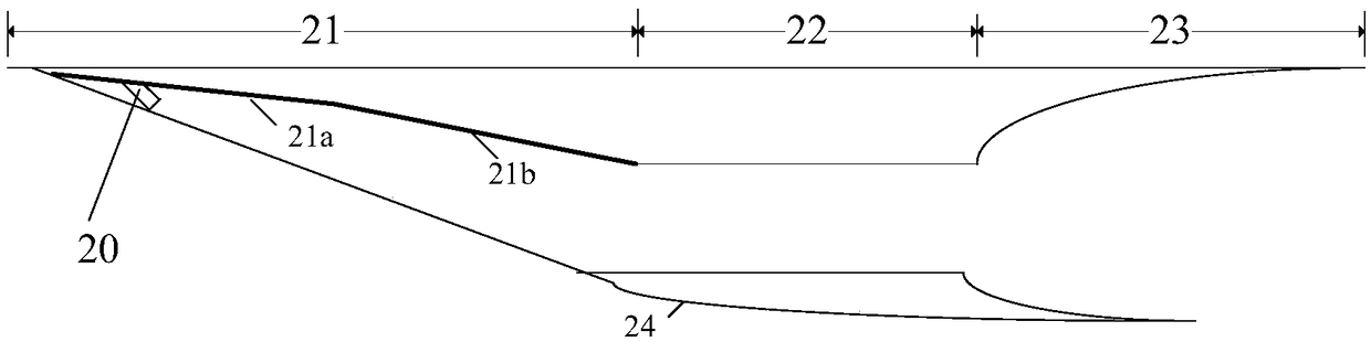
[0035] figure 2 It is a schematic diagram of the plane structure of a shock-induced ignition ramjet according to an embodiment of the present invention. The shock-induced-ignition ramjet engine includes: a fuel injector 20 , a three-dimensional lateral pressure intake port 21 with variable wedge surface, a combustion chamber 22 , and a tail nozzle 23 . A fuel injector 20 is arranged at the front end of the three-dimensional lateral pressure intake port 21 of the variable wedge surface. The variable wedge surface three-dimensional side pressure inlet 21 includes an upper wall surface and a side wall surface, and the upper wall surface includes a first wedge surface 21a and a second wedge surface 21b, wherein the slope of the second wedge surface 21b is greater than the slope of the first wedge surface 21a, The side wall is a retractable structure, and the side wall and the upper wall are connected by an arc transition.

[0036]Its working principle is that after the incoming...

Embodiment 2

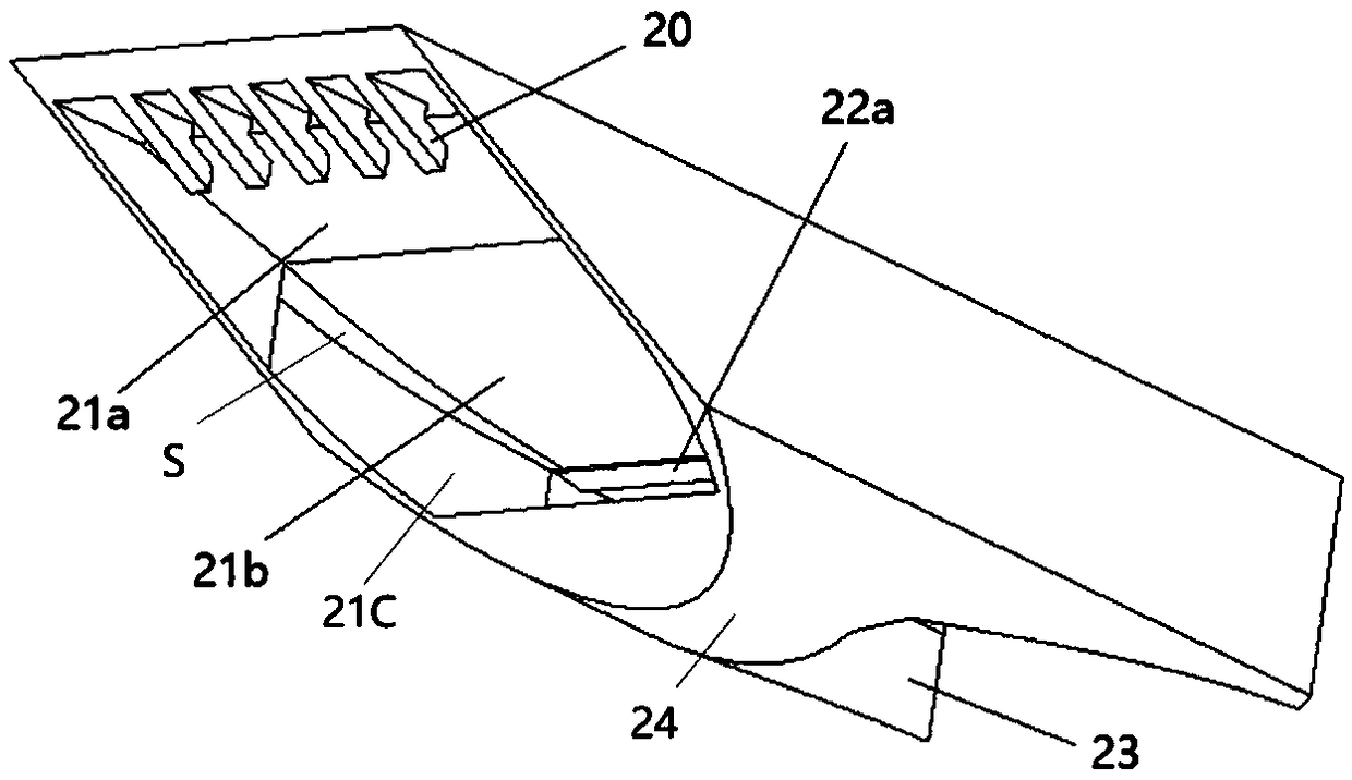
[0040] image 3 It is a three-dimensional structure schematic diagram of a shock wave induction ramjet according to an embodiment of the present invention. Specifically, the engine is arranged at the bottom of the fuselage, adopting an integrated design of the fuselage and the engine. The intake port includes a fuel injector 20 at the front end of the intake port, a first wedge surface 21a on the upper wall of the intake port, a second wedge surface 21b on the upper wall of the intake port, and a bottom fairing 24 . At the entrance of the combustion chamber 22, two flame-stabilizing support plates 22a with inclined planes are arranged. Combustion flame for stabilizing gas mixtures. The tail nozzle 23 is a gradually expanding tail nozzle.

[0041] Figure 4 , Figure 5 and Figure 6 The sectional view, top view and front view of the shock wave induction ramjet are respectively shown. The side wall surface 21c of the intake port adopts a retracted design to realize the co...

Embodiment 3

[0046] In this embodiment, the shock wave induced ramjet method includes the following steps:

[0047] The upper wall surface of the air inlet is configured to have a first wedge surface and a second wedge surface, and the slope of the second wedge surface is greater than the slope of the first wedge surface; the side wall surface of the air inlet is configured as an inward structure; The side wall surface and the upper wall of the inlet port are configured as an arc surface transition connection; the fuel injector is arranged on the surface of the first wedge surface, wherein the fuel injector is a transverse array cantilever injector; optionally , the tail nozzle is configured as a gradually diverging structure; when the hypersonic incoming flow enters the intake port, the fuel injector injects fuel; the hypersonic incoming flow is compressed in the inlet section formed by the side wall surface and the first wedge surface, At the same time, it is mixed with fuel, and then th...


PUM


Abstract

The invention discloses a shock wave combustion inducing ramjet and a shock wave combustion inducing stamping starting method. The ramjet comprises a variable-wedge-surface three-dimensional side pressure gas inlet way, a fuel injector, a combustion chamber and a tail spraying pipe. The variable-wedge-surface three-dimensional side pressure gas inlet way comprises an upper wall face and a side wall face. The upper wall face comprises a first wedge face and a second wedge face, wherein the slope of the second wedge face is larger than that of the first wedge face. The side wall face is of an inwards-contracting type structure, and the side wall face and the upper wall face are connected through arc transition. The fuel injector is arranged on the first wedge face, the combustion chamber communicates with the variable-wedge-surface three-dimensional side pressure gas inlet way, and the combustion chamber is not provided with the fuel injector. The tail spraying pipe communicates with thecombustion chamber. By means of the shock wave combustion inducing ramjet, combustion is organized in a detonation manner, the combustion distance is shorter, mixing and combustion of fuel and gas are more sufficient, the length of the combustion chamber can be designed to be shorter, and the pushing performance of the ramjet can be greatly improved.

Description

technical field [0001] The invention relates to the technical field of air-breathing hypersonic propulsion, in particular to a shock wave induction ramjet engine and a shock wave induction ramjet starting method. Background technique [0002] Hypersonic propulsion technology is the core key technology for the development of hypersonic vehicles. The scramjet is the best power device for hypersonic flight. figure 1 It is a schematic diagram of the current conventional scramjet engine. The scramjet engine includes an intake port 11 , a combustion chamber 12 and an exhaust pipe 13 . The combustion chamber 12 has a fuel injector 12a therein for injecting fuel. The working principle of the conventional scramjet engine is that the high-speed incoming flow enters the intake channel 11 and is compressed by the wedge surface of the upper wall to generate shock waves. The compressed shock wave enters the combustion chamber 12, and the fuel injector 12a provided at the front end of ...

Claims


Application Information

Patent Timeline
Patent Type & Authority Applications(China)
IPC IPC(8): F02K7/14F02C7/042
CPCF02C7/042F02K7/14
Inventor 滕宏辉郗雪辰
Owner BEIJING INSTITUTE OF TECHNOLOGYGY
Why Eureka
Try Eureka