
Visual detection device and method for blade pattern and surface defect

A visual inspection device and blade technology, applied in measurement devices, optical testing flaws/defects, instruments, etc., can solve the problems of inability to obtain surface texture or defect information, high speed of grinding and polishing equipment, poor imaging effect, etc., to improve detection Accuracy and efficiency, improving efficiency and automation, and solving the problem of incomplete imaging

Active Publication Date: 2018-12-18
HUAZHONG UNIV OF SCI & TECH
View PDF7 Cites 19 Cited by
  • Summary
  • Abstract
  • Description
  • Claims
  • Application Information

AI Technical Summary

Problems solved by technology

At present, the grinding and polishing process of blades is mostly done manually, the labor intensity is high, the dust pollution is serious, the high speed of grinding and polishing equipment is prone to accidents, and the requirements for the experience of the workers are relatively high, so there is an urgent need to develop automatic grinding and polishing in this field. method, as an intelligent manufacturing process, the detection and feedback of blade grinding and polishing quality are indispensable
[0003] The grinding and polishing of the blade removes the milling lines on the surface, so that when the metal blade surface is imaged, the reflection is strong, and the imaging effect of laser and structured light is relatively poor, and the surface texture or defect information cannot be obtained; while it is found in the ordinary CCD camera imaging test There is always a strong reflective area in the image, which affects the detection

Method used


Image

  • Visual detection device and method for blade pattern and surface defect
  • Visual detection device and method for blade pattern and surface defect

Examples


Embodiment Construction

[0030] In order to make the object, technical solution and advantages of the present invention clearer, the present invention will be further described in detail below in conjunction with the accompanying drawings and embodiments. It should be understood that the specific embodiments described here are only used to explain the present invention, not to limit the present invention. In addition, the technical features involved in the various embodiments of the present invention described below can be combined with each other as long as they do not constitute a conflict with each other.

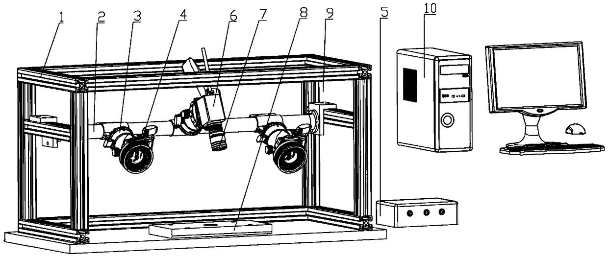
[0031] see figure 1 and figure 2 , the visual inspection device for blade lines and surface defects provided by the present invention, the visual inspection device includes a stand 1, a beam 2, a plurality of pan platforms 3, a plurality of light sources 4, a light source controller 5, a camera 6, a polarizer 7. Trigger mechanism 8, light shield 9 and microprocessor 10. Both ends of the cros...


PUM


Abstract

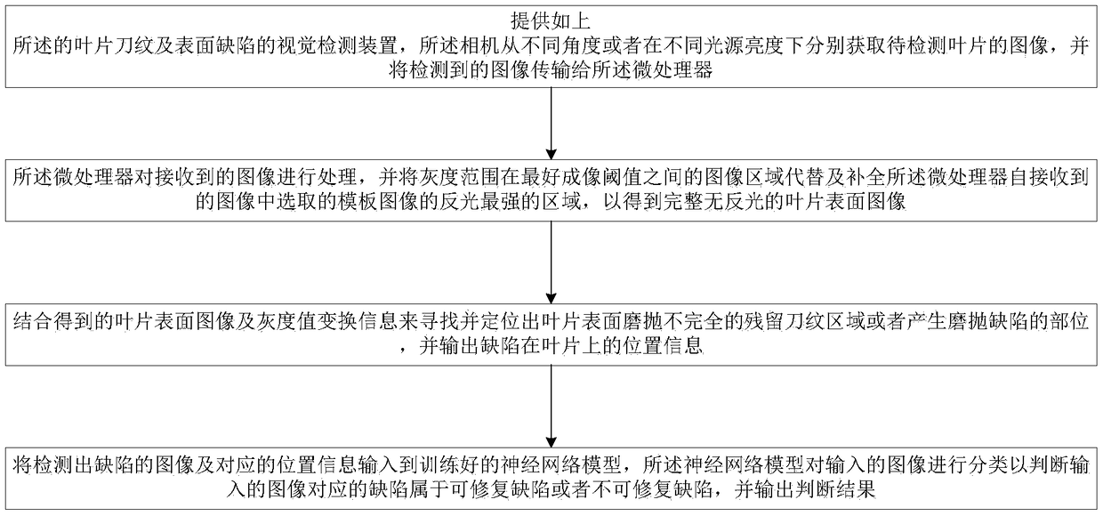
The invention belongs to the technical field of intelligent detection, and discloses a visual detection device and method for a blade pattern and a surface defect. The method comprises the following steps that (1) the visual detection device is provided, and a camera respectively acquires images of a to-be-detected blade from different angles or under different light source brightness and transmits the detected images to a microprocessor; (2) the microprocessor processes the received images and replaces and complements an area with the strongest light reflection of a template image selected from the received images by the microprocessor with an image area with the gray level range between the optimal imaging thresholds; (3) a residual pattern area with incomplete grinding and polishing onthe surface of a blade or a part for generating a grinding and polishing defect is found and positioned; and (4) a neural network model classifies the images with the detected defects in order to judge whether the defects corresponding to the input images can be repaired or not. According to the device and the method, the detection efficiency and accuracy are improved, the automation degree is high, and the cost is reduced.

Description

technical field [0001] The invention belongs to the technical field related to intelligent detection, and more specifically relates to a visual detection device and method for blade lines and surface defects. Background technique [0002] Blades directly participate in energy conversion in engines, compressors, gas turbines and other equipment, which is related to the performance and life of the overall equipment. In order to ensure smooth gas diversion, the surfaces of the blades are mostly free-form surfaces, which makes the processing and testing of the blades more difficult. In addition, as the blade is a key component, the processing quality of the blade surface is very high. At present, the grinding and polishing process of blades is mostly done manually, the labor intensity is high, the dust pollution is serious, the high speed of grinding and polishing equipment is prone to accidents, and the requirements for the experience of the workers are relatively high, so the...

Claims


Application Information

Patent Timeline
Patent Type & Authority Applications(China)
IPC IPC(8): G01N21/88
CPCG01N21/8806G01N21/8851G01N2021/8835G01N2021/8887
Inventor 赵欢陈茜李昊丁汉
Owner HUAZHONG UNIV OF SCI & TECH
Learn More