
Method for testing vertical radiation field type of target antenna

A radiation field type and test method technology, applied in the antenna radiation pattern and other directions, can solve problems such as antenna end damage, metal rust, equipment safety hazards, etc., to improve strength and work efficiency, test results are accurate and true, and solve antenna problems. The effect of terminal damage

Active Publication Date: 2018-12-18
CICIL AVIATION HUADONG NAVIGATION MANAGEMENT EQUIP INSTALLATION DEPT
View PDF10 Cites 10 Cited by
  • Summary
  • Abstract
  • Description
  • Claims
  • Application Information

AI Technical Summary

Problems solved by technology

However, in the prior art, there is no scientific and comprehensive test method for the antenna part of the old equipment in use, and for the test of the antenna of the equipment in use, the antenna can only be removed and sent to a professional test place (such as a microwave anechoic room). However, the disassembly of the antenna must be carried out after the machine is shut down, thus causing a hidden danger to the safety of the equipment
[0003] In addition, for antennas in use, especially old equipment, due to years of dirt accumulation, metal rust and other reasons, the antenna cannot be disassembled normally, and the work of disassembling the antenna may cause fatal damage to the antenna end

Method used


Image

  • Method for testing vertical radiation field type of target antenna
  • Method for testing vertical radiation field type of target antenna
  • Method for testing vertical radiation field type of target antenna

Examples


Embodiment Construction

[0049] The preferred embodiments of the present invention are given and described in detail below in conjunction with the accompanying drawings.

[0050] The present invention, namely a kind of testing method of target antenna vertical radiation pattern, it comprises the following steps:

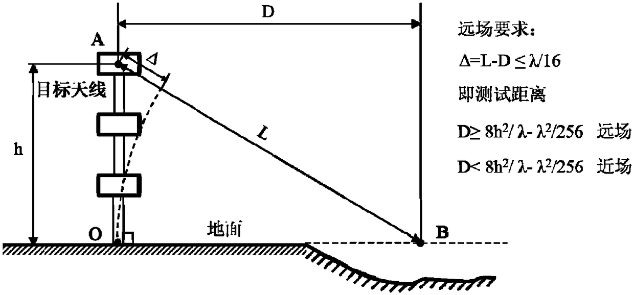
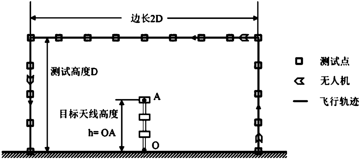
[0051] Step S1, determine the position of the target antenna by using the GPS device, including: the longitude and latitude of the target antenna; at the same time, according to the structure of the target antenna, determine the height of the target antenna by using a barometric altimeter: when the target antenna is a unit antenna, its height It is the vertical distance from its geometric center point to its position on the ground; when the target antenna is a vertically arranged array antenna, that is, when the target antenna contains multiple vertically arranged array units, its height is the highest array unit The vertical distance AO from the geometric center point A to its position poin...


PUM


Abstract

The invention relates to a method for testing a vertical radiation field type of a target antenna. The method includes the steps that a critical distance is calculated; a test distance and a flight parameter of a UAV are set; the UAV is made to take a position point of the target antenna on the ground as a square center and edges of the square on the ground as a flight path to fly around the target antenna in a vertical plane; space field strength data are tested at test points on the flight path of the UAV; the critical distance and the test distance are compared, and a far-field condition test or a near-field condition test is determined; and true vertical radiation field-type figures of the target antenna in the far and near fields are calculated correspondingly. According to the methodfor testing the vertical radiation field type of the target antenna, on the one hand, test of the antenna vertical radiation field type of a device without stopping the device can be realized so thatthe operating hidden trouble of the antenna of the device can be found in time, and the protection efforts and work efficiency of air traffic control equipment in use can be improved; and on the other hand, test with distribution characteristics of long distance and upper air sounding signals are realized, and the bottleneck of ground and air test in a near area is broken.

Description

technical field [0001] The invention relates to aeronautical radio measurement technology, in particular to a method for testing the vertical radiation pattern of a target antenna. Background technique [0002] At present, with the rapid development of China's aviation industry, the air traffic control communication, navigation and monitoring equipment is growing rapidly. Therefore, the requirements for equipment support are also getting higher and higher. However, in the prior art, there is no scientific and comprehensive test method for the antenna part of the old equipment in use, and for the test of the antenna of the equipment in use, the antenna can only be removed and sent to a professional test place (such as a microwave anechoic room). However, the disassembly of the antenna must be carried out after the machine is shut down, thus causing a hidden danger to the safety of the equipment. [0003] In addition, for antennas in use, especially old equipment, due to year...

Claims


Application Information

Patent Timeline
IPC IPC(8): G01R29/10
CPCG01R29/10
Inventor 白宇俊陆冉菁何勇解皓杰瞿淳清赵博李海铭高彦杰沈彦
Owner CICIL AVIATION HUADONG NAVIGATION MANAGEMENT EQUIP INSTALLATION DEPT
Learn More