
A two-dimensional convective thermal stealth cloak design method based on active control heat source

A design method and convective heat technology, applied in the fields of fluid mechanics and heat transfer, can solve the problems of thermal invisibility cloaks and difficult functions in the field of thermal convection.

Active Publication Date: 2018-12-18
XI AN JIAOTONG UNIV
View PDF7 Cites 12 Cited by
  • Summary
  • Abstract
  • Description
  • Claims
  • Application Information

AI Technical Summary

Problems solved by technology

However, for the three most basic forms of heat transfer: heat conduction, heat convection, and heat radiation, metamaterial heat cloaks are currently only applicable to heat conduction
If the coordinate transformation method and the design concept of metamaterials are applied to heat convection, when the fluid flows through a specific area, it is necessary to design the physical parameters with non-uniform anisotropy, and the original physical parameters need to be restored when the fluid flows out of the area. Difficult to achieve
Therefore, the coordinate transformation method of the traditional thermal cloak and the design concept of metamaterials cannot realize the thermal stealth cloak in the field of thermal convection.

Method used


Image

  • A two-dimensional convective thermal stealth cloak design method based on active control heat source
  • A two-dimensional convective thermal stealth cloak design method based on active control heat source
  • A two-dimensional convective thermal stealth cloak design method based on active control heat source

Examples


Embodiment Construction

[0093] combine first Figure 1-Figure 5 , the technical solution of the embodiment of the present invention is described as follows:

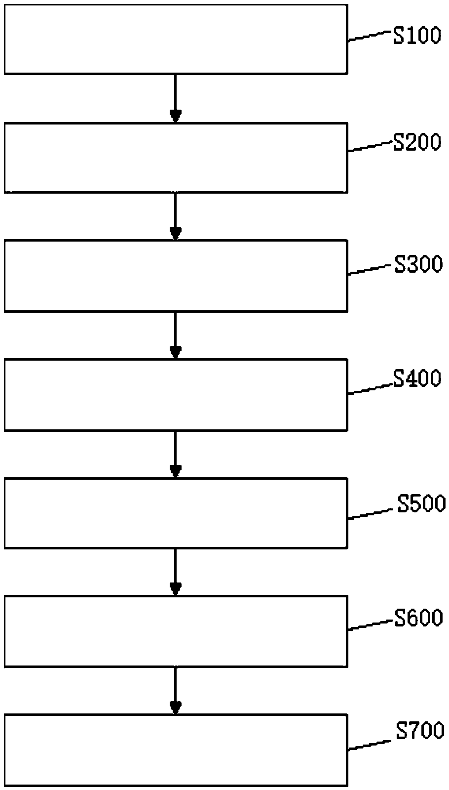
[0094] Such as figure 1 As shown, the embodiment of the present invention provides a two-dimensional convective thermal cloak design method based on active regulation and control of heat sources, including:

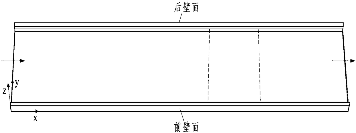
[0095] Step S100: Establish a three-dimensional coordinate system x-y-z, the fluid flows in from the left side of the flow channel, and flows out from the right side in the direction of the arrow, such as figure 2 shown. Set the inlet flow rate as u, set the front and rear walls of the flow channel as constant wall temperature, and set the wall temperature as T 1 and T 2 .

[0096] In this embodiment, the heat source is arranged on the plane of the runner z=0, and the distribution of the heat source is divided into regions, such as image 3 As shown, Z2 and Z3 are heat source areas, and Z1 and other areas are not treated. Set the b...


PUM


Abstract

The invention relates to a two-dimensional convective heat stealth cloak design method based on active control heat source, comprising the following steps of: establishing a three-dimensional coordinate system x-y-z and determining that the region surrounded by the coordinate system is a design region. The velocity distribution and background temperature of the flow field are calculated. The direct problem, the adjoint problem, the derivative of the objective function, the conjugate coefficient, the iterative direction coefficient, the sensitivity problem, the iterative step length and the objective function of the heat source in Z2 and Z3 regions are solved respectively, and the heat source distribution is updated. The composite objective functions of Z2 and Z3 regions are calculated. According to the flow field velocity and the background temperature, the invention establishes a stealth cloak by applying a heat source at the bottom of the flow channel, and heats or cools the fluid flowing in a specific area, so as to realize the temperature distribution in the flow field that satisfies the function of the stealth cloak.

Description

technical field [0001] The invention belongs to the fields of fluid mechanics and heat transfer, and in particular relates to a design method for a two-dimensional convective heat stealth cloak based on active regulation and control of heat sources. Background technique [0002] The problem of heat flow stealth is another emerging field after the rapid development of electromagnetic wave and sound wave stealth. Since the heat conduction equation and Maxwell's equation also have form invariance, inspired by the electromagnetic cloak (Pendry J B, et al, Science, 2006, 312(5781): 1780-1782), the coordinate transformation method was extended to the field of heat transfer, Through the design of physical parameters, a thermal invisibility cloak based on metamaterials was developed. However, for the three most basic forms of heat transfer: heat conduction, heat convection, and heat radiation, metamaterial heat cloaks are currently only applicable to heat conduction. If the coordi...

Claims


Application Information

Patent Timeline
Patent Type & Authority Applications(China)
IPC IPC(8): G06F17/50G06T17/00
CPCG06F30/17G06T17/00
Inventor 屈治国郭君
Owner XI AN JIAOTONG UNIV
Learn More