
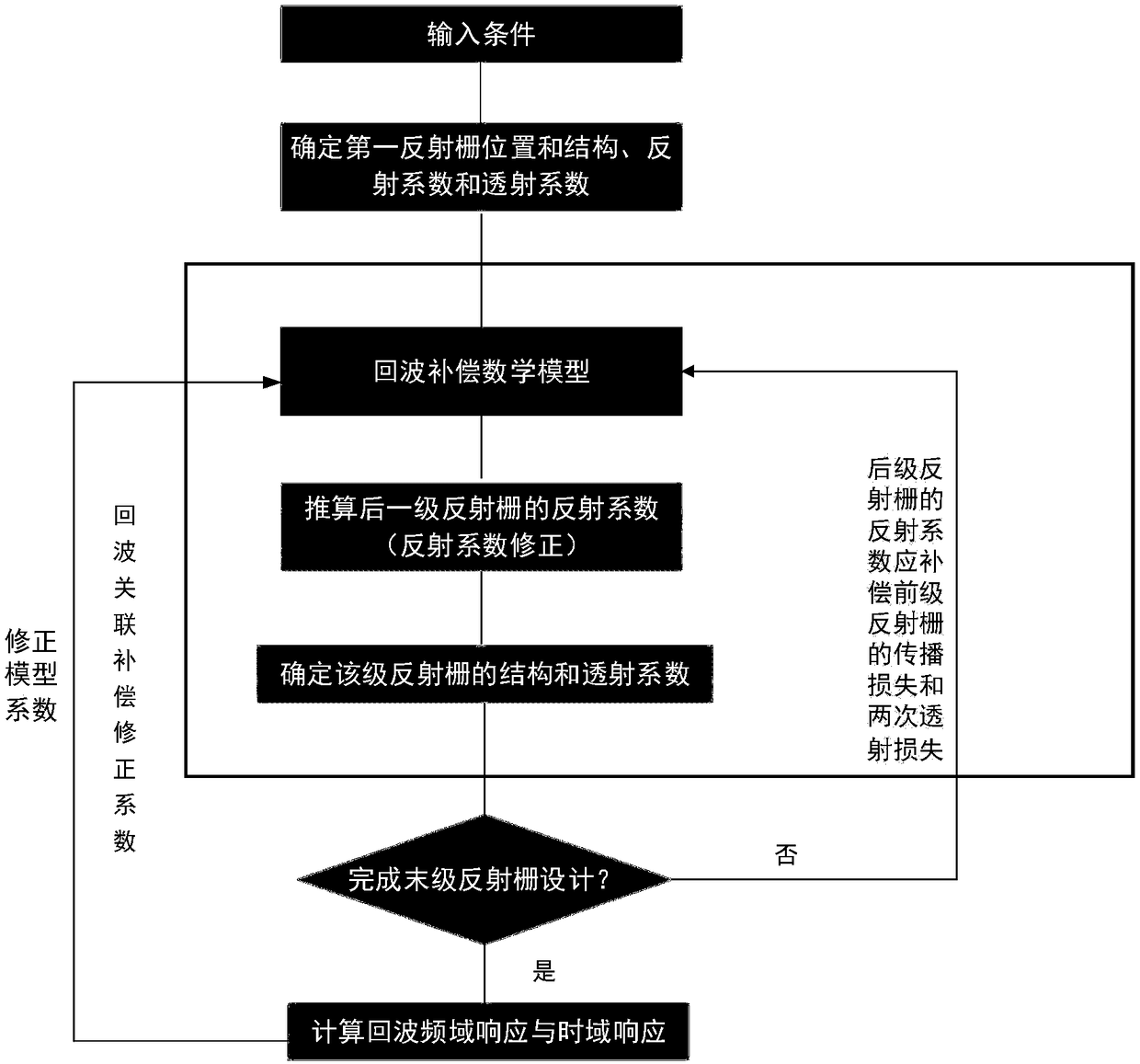
Surface acoustic wave RFID chip reflection coefficient design method based on echo energy compensation

A technology of reflection coefficient and surface acoustic wave, applied in CAD circuit design, design optimization/simulation, calculation, etc., to achieve good detection and recognition effect, good echo performance, and the effect of mass production and preparation

Active Publication Date: 2018-12-18
NO 719 RES INST CHINA SHIPBUILDING IND
View PDF3 Cites 0 Cited by
  • Summary
  • Abstract
  • Description
  • Claims
  • Application Information

AI Technical Summary

Problems solved by technology

How to design and determine the reflection coefficient of the reflective grating so that the corresponding propagation loss and transmission loss can be compensated to ensure the consistency of the echo energy (amplitude) of the reflective gratings at all levels has not been well resolved.

Method used


Image

  • Surface acoustic wave RFID chip reflection coefficient design method based on echo energy compensation
  • Surface acoustic wave RFID chip reflection coefficient design method based on echo energy compensation
  • Surface acoustic wave RFID chip reflection coefficient design method based on echo energy compensation

Examples


Embodiment Construction

[0025] The present invention will be described in detail below with reference to the accompanying drawings and examples.

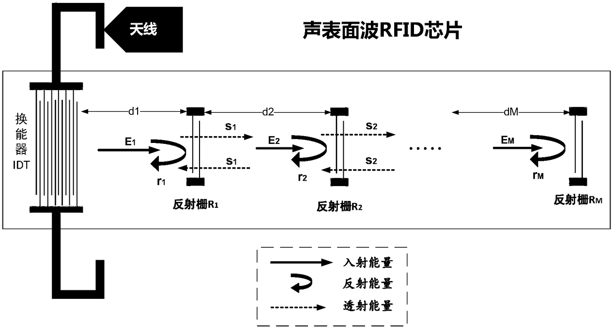
[0026] The present invention provides a method for designing the delay line reflection coefficient of a surface acoustic wave RFID chip based on echo energy compensation. For a surface acoustic wave RFID chip in a pulse position encoding mode, a mathematical model of echo compensation is established to guide the design of each The reflection coefficient of the first-stage reflection grating, its core idea is to compensate the propagation loss and the two transmission losses of the previous-stage reflection grating with the reflection coefficient of the rear-stage reflection grating, so as to ensure the consistency of the echo energy (amplitude) of each level of reflection grating, and obtain Better detection and recognition effect.

[0027] The overall structure of the surface acoustic wave RFID chip is as follows: figure 2 As shown, including 1 IDT tran...


PUM


Abstract

The invention discloses a surface acoustic wave RFID chip reflection coefficient design method based on echo energy compensation. By using the invention, the requirements of the delay line structure can be met and the echo performance of each level of the reflection grating can be ensured, so that a better detection and identification effect can be obtained. The influence of the propagation loss and the secondary transmission loss of the front reflector on the reflected echo energy of the back reflector is fully considered. By establishing a mathematical model of echo compensation to eliminatethe influence of the propagation loss and the secondary transmission loss of the front reflector on the reflected echo energy of the back reflector, compared with the existing design method, the SAWelectronic tag chip designed by the method of the invention has better echo quality, detection and identification effect and higher design efficiency.

Description

technical field [0001] The invention relates to the technical field of surface acoustic wave (SAW) radio frequency identification (RFID), relates to a method for designing the reflection coefficient of a delay line reflection grating of a surface acoustic wave chip, and in particular to a surface acoustic wave electronic device with echo energy compensation capability A design method for the characteristic parameters of the tag chip reflective grid. Background technique [0002] The surface acoustic wave RFID chip is the core device of the radio frequency identification electronic tag based on the surface acoustic wave technology. Because the RFID chip of the surface acoustic wave electronic tag does not involve the carrier movement of the traditional IC-type electronic tag RFID chip, it has natural adaptability to harsh environmental conditions such as high temperature, high pressure, radiation, and strong electromagnetic interference, and has passive, The advantages of wi...

Claims


Application Information

Patent Timeline
Patent Type & Authority Applications(China)
IPC IPC(8): G06F17/50
CPCG06F30/39G06F30/20
Inventor 阎毓杰王楠杨云涛邢思玮王红军
Owner NO 719 RES INST CHINA SHIPBUILDING IND
Learn More