Broadband Multi-Patch Antenna

A multi-patch and antenna technology, applied in the direction of antenna, antenna coupling, antenna components, etc., can solve the problems of single-patch antenna narrow bandwidth, limited lifting capacity, low radiation efficiency, etc., to suppress back radiation, reduce Gain fluctuations, reducing the effect of cross-polarized signals

Active Publication Date: 2021-01-01
南通大学技术转移中心有限公司
View PDF6 Cites 0 Cited by
  • Summary
  • Abstract
  • Description
  • Claims
  • Application Information

AI Technical Summary

Problems solved by technology

[0004] In short, the traditional single-patch antenna has a narrow bandwidth and low gain. Multi-patch antennas can effectively increase the bandwidth, but the existing multi-patch antennas have a limited ability to increase the bandwidth, and the bandwidth is about 29%. The reason is that the effective The number of working modes, either only two working modes exist, or one of the three modes has low radiation efficiency

Method used

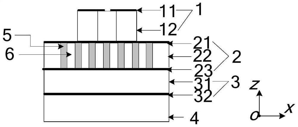
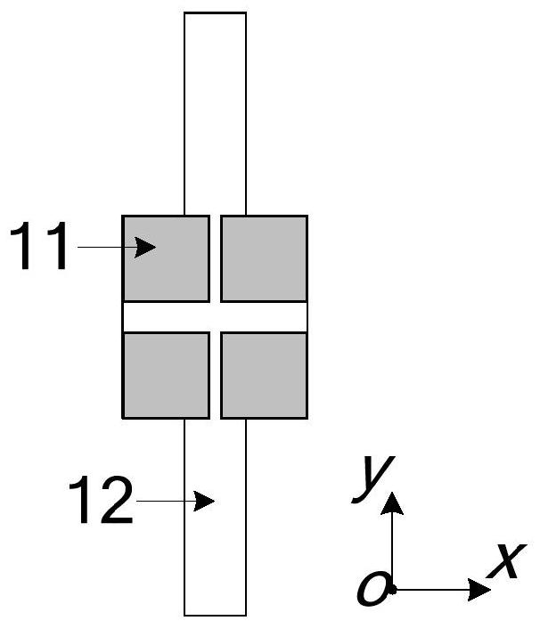
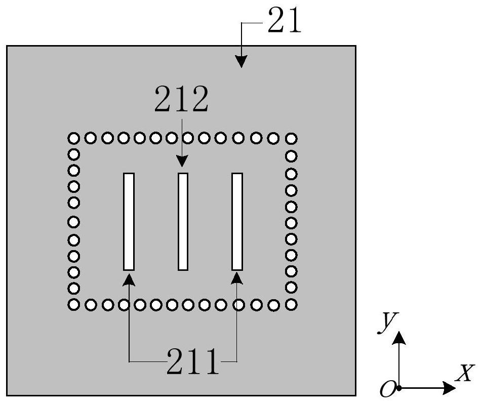

Image

  • Broadband Multi-Patch Antenna
  • Broadband Multi-Patch Antenna
  • Broadband Multi-Patch Antenna

Examples


Embodiment Construction

[0024] In order to facilitate the understanding of the present invention, the present invention will be described more fully below with reference to the associated drawings. Typical embodiments of the invention are shown in the drawings. However, the present invention can be embodied in many different forms and is not limited to the embodiments described herein. Rather, these embodiments are provided so that the disclosure of the present invention will be thorough and complete.

[0025] It should be noted that the terms "vertical", "horizontal", "left", "right" and similar expressions used herein are for illustrative purposes only. Unless otherwise defined, all technical and scientific terms used herein have the same meaning as commonly understood by one of ordinary skill in the technical field of the invention. The terms used herein in the description of the present invention are for the purpose of describing specific embodiments only, and are not intended to limit the pres...


PUM


Abstract

The invention discloses a broadband multi-patch antenna, which includes sequentially arranged from top to bottom: a first layer structure, including a top layer multi-patch structure; a second layer structure, including a substrate integrated resonant cavity, and a substrate integrated resonant cavity The top is provided with a top middle groove and two side grooves, the bottom is provided with a bottom middle groove, and the two side grooves are arranged on both sides of the top middle groove and are symmetrical about the top middle groove; the third layer structure, including the feed structure, is used for Feed and couple the signal into the substrate integrated resonant cavity through the bottom middle slot, thereby exciting the mode signal, which radiates through the two side slots and couples with the first mode of the top multi-patch structure, At the same time, the mode signal is also coupled to the first mode and the second mode of the top multi-patch structure through the top middle groove. The invention can generate three effective radiation working modes to further expand the working bandwidth of the antenna, and can also realize efficient cavity-backed slot radiation to reduce gain fluctuation in the antenna band.

Description

technical field [0001] The invention relates to the communication field, in particular to a broadband multi-patch antenna. Background technique [0002] Patch antennas are widely used in wireless communication systems because of their low profile, small size, easy integration with other circuits, and low processing costs. The traditional single-patch antenna has narrow bandwidth and low gain, while the antenna formed by the multi-patch structure fed by the slot coupling structure can effectively expand the antenna bandwidth and increase the antenna gain. [0003] At present, there are various forms of multi-patch antennas fed by slot coupling. For example, the antenna composed of slot-coupled 4×4 uniform multi-metal patches can excite two modes, respectively TM 10 mode with inverting TM 20 mode, the relative bandwidth can reach 28%; the antenna formed by the slot-fed diamond-shaped slotted metal patch can also excite two modes to form a broadband, and the two modes are qua...

Claims


Application Information

Patent Timeline
Patent Type & Authority Patents(China)
IPC IPC(8): H01Q1/38H01Q1/50H01Q1/52
CPCH01Q1/38H01Q1/50H01Q1/526
Inventor 施金孟春梅张威曹青华徐凯陈燕云陈建新
Owner 南通大学技术转移中心有限公司
Why Eureka
Try Eureka