A planar annular microstrip slow-wave structure
A slow-wave structure and ring-shaped technology, which is applied to the circuit components of the time-of-flight tube, can solve the problem of narrow frequency band, achieve wide working bandwidth, reduce requirements, and achieve the effect of small gain fluctuation
- Summary
- Abstract
- Description
- Claims
- Application Information
AI Technical Summary
Problems solved by technology
Method used
Image
Examples
Embodiment
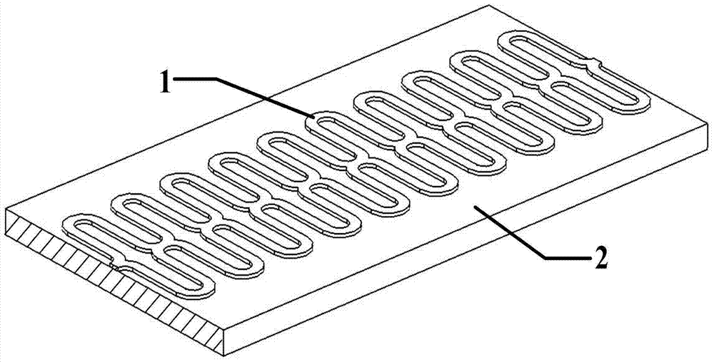
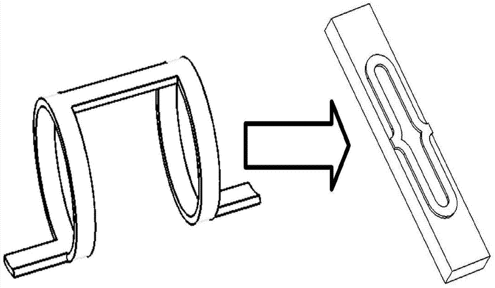
[0029] A planar annular slow-wave structure, such as figure 1 As shown, this figure is a structural schematic diagram of a specific embodiment of the present invention, including a dielectric substrate 2 and a metal wire 1 located on the surface of the dielectric substrate 2, and the metal wire 1 is sequentially connected by a plurality of ring units with the same shape and size A periodic structure is formed, each ring unit is formed by butting two split rings with upper and lower mirror mirrors, and two adjacent ring units are connected by a microstrip line at the junction of the two split rings.
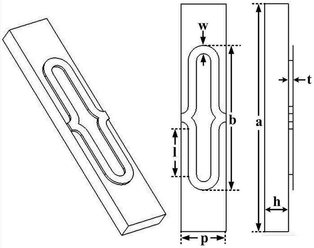
[0030] Such as figure 2 As shown, the dimension of the above-mentioned planar annular microstrip slow-wave structure is defined as follows: the dielectric constant of the dielectric substrate 2 is ε, the thickness of the dielectric substrate is h, the line width of the metal wire 1 is w, and the thickness is t, and the metal microstrip The transverse length of the belt loop is b...
PUM
 Abstract
Description
Claims
Application Information
 - R&D
- Intellectual Property
- Life Sciences
- Materials
- Tech Scout
- Unparalleled Data Quality
- Higher Quality Content
- 60% Fewer Hallucinations
Browse by: Latest US Patents, China's latest patents, Technical Efficacy Thesaurus, Application Domain, Technology Topic, Popular Technical Reports.
© 2025 PatSnap. All rights reserved.Legal|Privacy policy|Modern Slavery Act Transparency Statement|Sitemap|About US| Contact US: help@patsnap.com


