Eureka AIR delivers breakthrough ideas for toughest innovation challenges, trusted by R&D personnel around the world.

Falling-film reactor

A falling film reactor and reactor shell technology, applied in membrane technology, chemical instruments and methods, gas treatment, etc., can solve the problem of uneven liquid distribution on the inner wall of the guide tube

Pending Publication Date: 2018-12-21
CHONGQING SHANJU CHEM MACHINERY
View PDF0 Cites 2 Cited by
  • Summary
  • Abstract
  • Description
  • Claims
  • Application Information

AI Technical Summary

Problems solved by technology

[0004] The purpose of the present invention is to provide a falling film reactor to solve the problem of uneven liquid distribution on the inner wall of the draft tube

Method used


Image

  • Falling-film reactor
  • Falling-film reactor
  • Falling-film reactor

Examples


Embodiment Construction

[0022] The following is further described in detail through specific implementation methods:

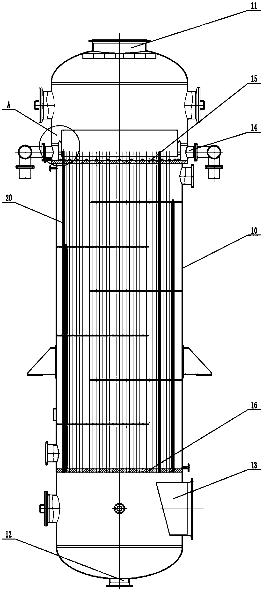
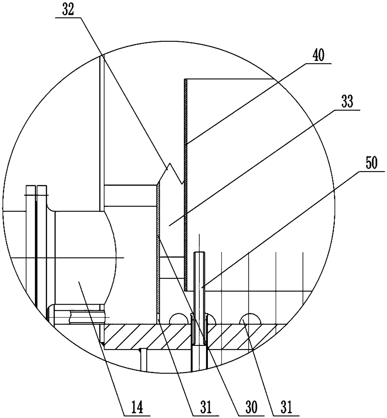
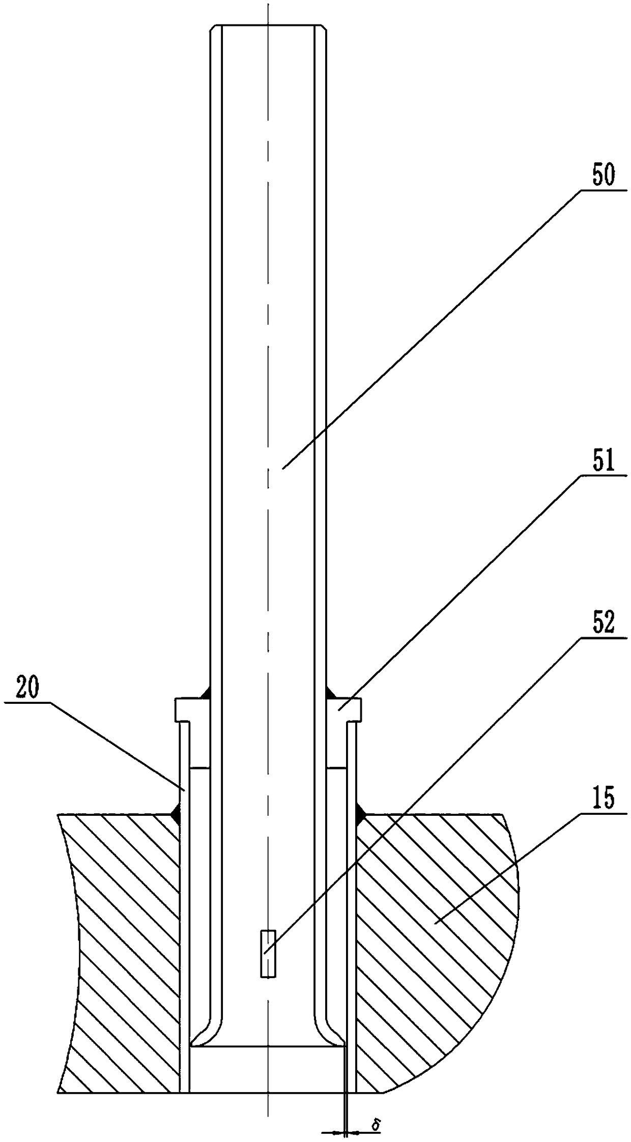
[0023] Instructions attached Figures 1 to 5 The reference signs in include: reactor shell 10, air inlet 11, liquid outlet 12, air outlet 13, liquid inlet 14, upper tube plate 15, lower tube plate 16, draft tube 20, liquid separation Barrel 30 , through hole 31 , zigzag groove 32 , flow channel 33 , overflow plate 40 , falling film reaction head 50 , L-shaped stop block 51 , center positioning block 52 , and liquid channel 60 .

[0024] Such as figure 1 , figure 2 Shown, a kind of falling film reactor comprises reactor shell 10, and the top of reactor shell 10 has air inlet 11, and the bottom of reactor shell 10 has liquid outlet 12, and reactor shell 10 The upper side wall is provided with a plurality of liquid inlets 14 , in this embodiment, there are eight liquid inlets 14 , and the eight liquid inlets 14 are evenly distributed along the circumference of the side wall of the r...


PUM


Abstract

The invention belongs to the technical field of an absorption reaction device, and particularly discloses a falling-film reactor. The falling-film reactor comprises a reactor shell, wherein the upperside wall of the reactor shell is provided with a liquid inlet, an upper pipe plate and a lower pipe plate are fixed in the reactor shell, the upper pipe plate is located on the upper part of the reactor shell and located below the liquid inlet, and the lower pipe plate is located on the lower part of the reactor shell; the upper pipe plate is provided with a liquid distribution drum, and a plurality of flow guide pipes are arranged between the upper pipe plate and the lower pipe plate in a penetrating manner; the lower side wall of the liquid distribution drum is provided with a plurality ofthrough holes, and the top side wall of the liquid distribution drum is provided with a plurality of sawtooth-shaped grooves; an overflow plate located in the liquid distribution drum is arranged above the upper pipe plate, a flow passage is formed between the liquid distribution drum and the overflow plate, the flow guide pipe is located in the overflow plate, the top of the overflow plate is located above the liquid distribution drum, and the height of the bottom of the overflow plate is lower than the height of the upper part of the flow guide pipe; and a falling film apparatus is arrangedin the upper part of the flow guide pipe. By utilizing the falling film reactor of the invention, uniformity in film falling can be realized, and the dry pipe phenomenon can be effectively avoided.

Description

technical field [0001] The invention belongs to the technical field of absorption reaction equipment, in particular to a falling film reactor. Background technique [0002] Some poisonous and harmful gases will be produced in the chemical production process. The existence of these gases not only pollutes the environment, but also endangers human health. Therefore, these gases need to be treated before being discharged. At present, absorption reactors are generally used to deal with these harmful gases. Absorption reactor is a kind of high-efficiency energy-saving equipment, which is widely used in the production of chemical industry, refrigeration, waste heat recovery and other industries. Falling film reactor is a kind of absorption reactor. The existing falling film reactor generally has a liquid inlet on the side of the shell. The liquid enters the liquid distribution plate from the liquid inlet, and after forming a certain liquid level on the liquid distribution plate, i...

Claims


Application Information

Patent Timeline
Patent Type & Authority Applications(China)
IPC IPC(8): B01D53/78
CPCB01D53/78B01D2258/02
Inventor 秦中贤
Owner CHONGQING SHANJU CHEM MACHINERY
Why Eureka
Eureka Blog
Learn More