Blind hole boring cutter assembly

A boring tool and component technology, applied in the field of blind hole boring tool components, can solve the problems of increasing chip removal, easy wear of alloys, and chattering of tool bars, and achieves the effects of reducing scrap rate, reducing friction and eliminating vibration.

Pending Publication Date: 2018-12-21
西安鑫旺矿业设备有限公司
View PDF0 Cites 0 Cited by
  • Summary
  • Abstract
  • Description
  • Claims
  • Application Information

AI Technical Summary

Problems solved by technology

[0007] The purpose of the present invention is to solve the problems in the prior art that when the boring tool is cutting the hole, the alloy is easy to wear, the debris is increased, and even the tool rod vibrates during operation, and a blind hole boring tool assembly is provided.

Method used


Image

  • Blind hole boring cutter assembly
  • Blind hole boring cutter assembly
  • Blind hole boring cutter assembly

Examples


Embodiment 2

[0051] Refer to attached Figure 4 As shown, as a further improvement of the above-mentioned embodiment, in this embodiment, the above-mentioned support block 5 is changed to a screw, that is, several screw holes are opened on the outer periphery of the rotating body 2, and the screw is threadedly connected to the screw holes. Specifically, the length of the screw is 40mm-120mm. Generally, in order to reduce the weight, the volume of the rotating body 2 is small, and the distance between the rotating body 2 and the inside of the hole is relatively large, so the length of the screw can also be adjusted accordingly.

[0052] In this embodiment, a lock nut 10 is added outside the screw hole, and the screw rod is locked through the lock nut 10, so as to avoid the shaking of the screw rod during rotation, so that it is locked on the outer periphery of the rotating body 2, and the connection stability is improved. .

[0053] In this example, refer to the attached Figure 5 As sho...

Embodiment 3

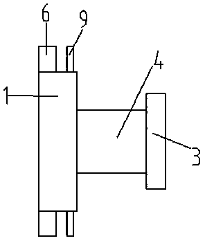
[0057] Refer to attached image 3 As shown, as a further supplement to the above-mentioned embodiment, in this embodiment, the main body 1 of the cutter head is selected to be a square or disc-shaped structure. Refer to attached Figure 6 Shown, select disc-shaped cutter head main body 1 now, offer chute 13 on cutter head main body 1, cutter head 6 is placed in chute 13, two cutter heads 6 are placed in one chute 13.

[0058] At least two screws 14 are arranged on the sides of each chute 13 , and the screws 14 abut against the cutter head 6 , and the length of the cutter head 6 can be adjusted by unscrewing or locking the screws 14 . For example, when the length needs to be adjusted, the screw 14 is unscrewed, and now the cutter head 6 moves freely in the chute 13, adjusted to a suitable position, then the screw 14 is tightened, and the cutter head 6 is locked in the chute.

[0059] Refer to attached image 3 As shown, in the present embodiment, in order to realize the cool...

Embodiment 4

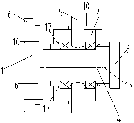
[0063] As a further improvement of any of the above embodiments, refer to the attached image 3 As shown, in this embodiment, the rotating body 2 adopts a bearing, specifically a tapered roller bearing, and a flange is arranged outside the bearing, and the flange is fixedly connected with the bearing through a nut, etc. The nut is provided with a sealing ring 17. When the rotating body 2 rotates, the additional sealing ring 17 prevents foreign matters from entering the bearing and reduces the service life of the bearing. During installation, the whole is connected with the flange of the tool holder through pin positioning and thread fastening.

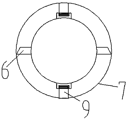
[0064] When in use, the bearing and the pipe 7 rotate in the same direction and at the same speed, while the cutter head body 1 and the cutter bar 3 only move horizontally instead of circularly, which reduces the wear on the support block 5 .


PUM


Abstract

The invention provides a blind hole boring cutter assembly. The blind hole boring cutter assembly comprises a cutter head main body, a rotating body, a cutter rod and a rotating shaft. A cutter head is arranged on the periphery of the cutter head main body and used for cutting a hole inner wall. The rotating body is used for rotating the cutter head during cutting, a plurality of height-adjustablesupporting blocks are arranged on the periphery of the rotating body, and during cutting of the cutter head, the supporting blocks make contact with the hole inner wall. The cutter rod is provided with a hand-held part. The rotating shaft penetrates through the rotating body, and the two ends of the rotating shaft are connected with the cutter head main body and the cutter rod correspondingly. When the cutter head cuts the hole inner wall, a hole of a machining piece rotates, the cutter head main body and the cutter rod move in the horizontal direction and simultaneously rotate with the holein the same direction under driving of static friction force, and the rotating speed of the rotating body is the same as that of the hole; and when the cutter head cuts the hole inner wall, the rotating speed of the hole of the machining piece is 50-300 r/min. The blind hole boring cutter assembly has the effects that friction of the supporting blocks is reduced, vibration is eliminated, and chipremoving is facilitated.

Description

technical field [0001] The invention belongs to the field of boring cutters, in particular to a blind hole boring cutter assembly. Background technique [0002] Blind hole boring tool in the prior art, with reference to attached figure 1 As shown, including the main body of the cutter head, the connecting plate, the tool rod and the alloy block arranged on the connecting plate, the thickness of the alloy is about 5mm; it is mainly used for cutting or processing pipes with equal thickness, such as pipes with an inner diameter of 225mm , cutting or processing to the inner diameter of 230mm, at this time, the inner wall of the pipe needs to be cut or processed. During use, the alloy on the connection plate is in contact with the inner wall of the pipe, the pipe is rotated, the boring tool starts to work, and the inner wall of the workpiece rubs against the supporting alloy block , as time goes on, the alloy block wears out quickly, causing a gap between the alloy block and the...

Claims


Application Information

Patent Timeline
Patent Type & Authority Applications(China)
IPC IPC(8): B23B27/00
CPCB23B27/00B23B27/002
Inventor 蒲天娃李富佳
Owner 西安鑫旺矿业设备有限公司
Why Eureka
Try Eureka