
Laser marking method for hard and brittle materials

A laser marking method and technology for hard and brittle materials, applied in the field of laser marking of hard and brittle materials, can solve problems such as affecting the clarity of marking and material cracking, and achieve the effect of improving clarity and avoiding cracking

Active Publication Date: 2018-12-21
江苏峰钛激光科技有限公司
View PDF8 Cites 1 Cited by
  • Summary
  • Abstract
  • Description
  • Claims
  • Application Information

AI Technical Summary

Problems solved by technology

[0002] The cost of fiber laser marking machine is low, and it has been widely used in plastic, steel and other materials. However, when optical fiber is used for laser marking on hard and brittle materials such as glass and ceramics, due to the thermal The laser marking area on the surface of brittle materials is prone to micro-cracks, and these cracks perpendicular to the direction of laser movement will form new cracks, which will expand to the area near the original mark and form fragments, thereby affecting the clarity of the mark, and even breaking the material in severe cases

Method used


Image

  • Laser marking method for hard and brittle materials
  • Laser marking method for hard and brittle materials

Examples


Embodiment 1

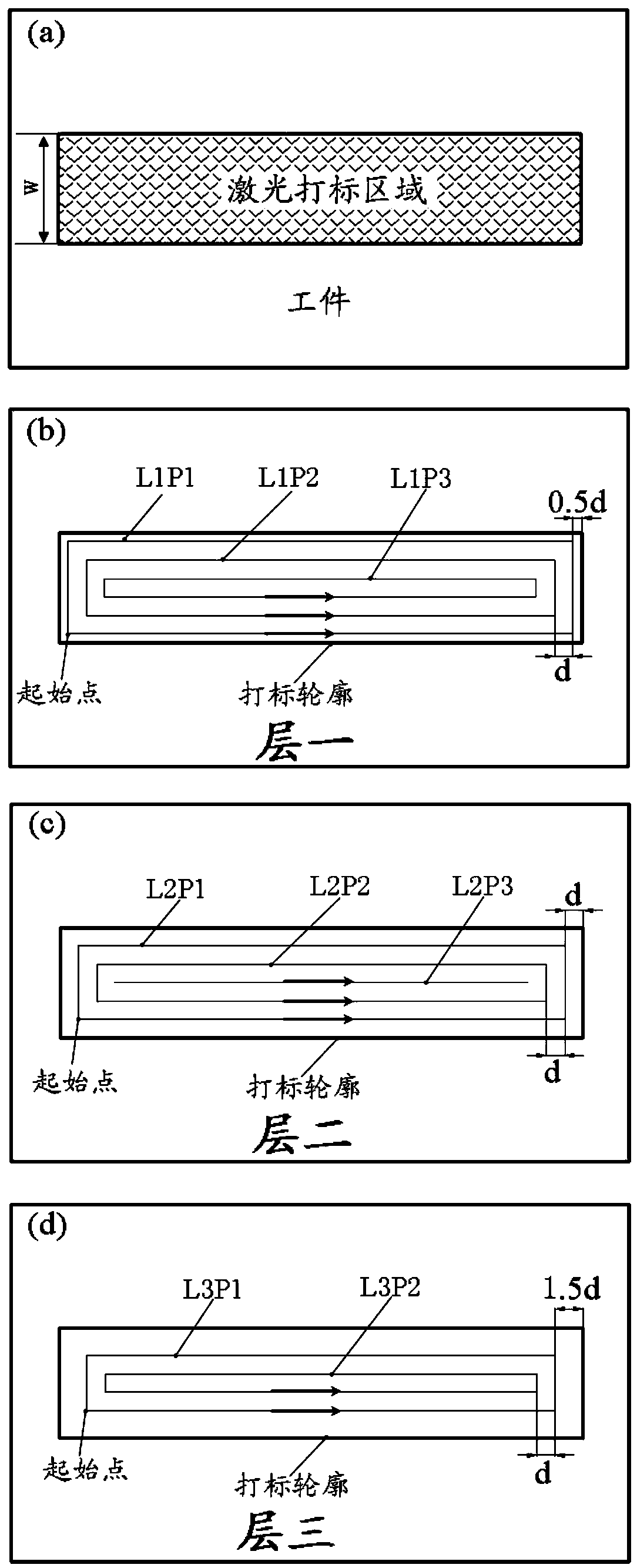
[0022] In this example, the laser is a pulsed fiber laser, the single pulse energy of the laser is 0.5mJ, the frequency is 20KHZ, the pulse width of the laser beam is 10ns, the wavelength is 1064nm, the laser spot diameter is 0.05mm, the scanning speed is 1m / s, and the hard and brittle material is silicon nitride. Laser marking on the surface of the workpiece such as figure 2 The figure shown in (a) has a width W of 0.28mm and a length of 5mm. Specific steps are as follows:

[0023] Step 1: Input the required graphics or characters into the marking software, set the laser scanning path to scan along the boundary, and the scanning method is from outside to inside;

[0024] Step 2: The number of laser scanning paths n=W / 2d=2.8, rounding n to 3;

[0025] Step 3: With the laser parameters, from figure 2 (b) Start scanning from the starting point of the scanning path L1P1, and the distance between the centers of adjacent scanning paths is 0.05mm. After scanning L1P1, continue...

Embodiment 2

[0030] In this example, the laser is a pulsed fiber laser, the single pulse energy of the laser is 0.75mJ, the frequency is 35KHZ, the pulse width of the laser beam is 50ns, the wavelength is 1064nm, the diameter of the laser spot is 0.05mm, and the scanning speed is 1.25m / s. Hard and brittle materials for silicon nitride. Laser marking on the surface of the workpiece such as figure 2 The figure shown in (a) has a width W of 0.28mm and a length of 5mm. Specific steps are as follows:

[0031] Step 1: Input the required graphics or characters into the marking software, set the laser scanning path to scan along the boundary, and the scanning method is from outside to inside;

[0032] Step 2: The number of laser scanning paths n=W / 2d=2.8, rounding n to 3;

[0033] Step 3: With the laser parameters, from figure 2 (b) Start scanning from the starting point of the scanning path L1P1, and the distance between the centers of adjacent scanning paths is 0.05mm. After scanning L1P1,...

Embodiment 3

[0038] In this example, the laser is a pulsed fiber laser, the single pulse energy of the laser is 1mJ, the frequency is 50KHZ, the pulse width of the laser beam is 10ns, the wavelength is 1064nm, the diameter of the laser spot is 0.05mm, the scanning speed is 1.5m / s, and the hard and brittle material is silicon nitride. Laser marking on the surface of the workpiece such as figure 2 The figure shown in (a) has a width W of 0.28mm and a length of 5mm. Specific steps are as follows:

[0039] Step 1: Input the required graphics or characters into the marking software, set the laser scanning path to scan along the boundary, and the scanning method is from outside to inside;

[0040] Step 2: The number of laser scanning paths n=W / 2d=2.8, rounding n to 3;

[0041] Step 3: With the laser parameters, from figure 2 (b) Start scanning from the starting point of the scanning path L1P1, and the distance between the centers of adjacent scanning paths is 0.05mm. After scanning L1P1, con...


PUM

PropertyMeasurementUnit
lengthaaaaaaaaaa

Abstract

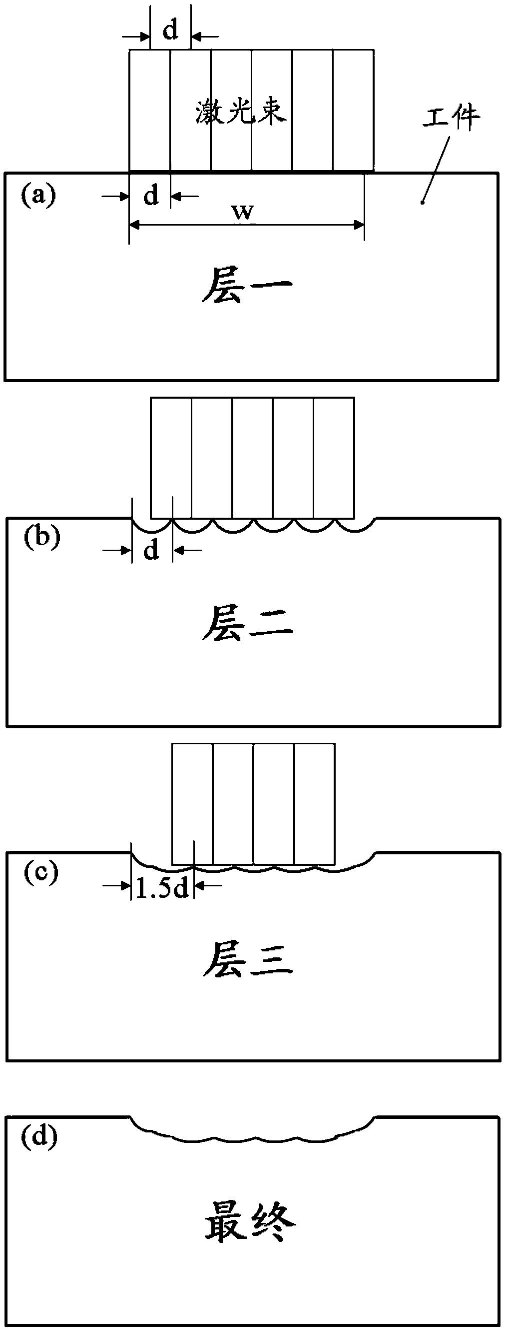
The invention discloses a laser marking method for hard and brittle materials. The surfaces of three layers of ablation hard and brittle materials are marked to guarantee enough depths of laser marking marks to achieve a visual effect; a distance from a center line of a laser beam on the outermost side of the second layer to the edge of the outermost side of the first layer is d, and a distance from a center line of a laser beam on the outermost side of the third layer to the edge of the outermost side of the first layer is 1.5 d, so that a residual height after previous laser scanning can beeffectively removed through laser scanning of the second layer and the third layer, and meanwhile, scanning widths among the first layer, the second layer and the third layer are gradually reduced toachieve gentle transition of the edges among the layers; and distances between center lines of adjacent laser scanning paths in the same layers are d, so that clear separation lines can be formed between the adjacent scanning paths, the grinding effect is achieved under illumination, and the marking clearness is further improved. Nicks without micro cracks and with clear marks are finally obtained. The laser marking method can be applied to the surfaces of the hard and brittle materials.

Description

technical field [0001] The invention relates to the field of surface treatment, in particular to a laser marking method for hard and brittle materials. Background technique [0002] The cost of fiber laser marking machine is low, and it has been widely used in plastic, steel and other materials. However, when optical fiber is used for laser marking on hard and brittle materials such as glass and ceramics, due to the thermal The laser marking area on the surface of brittle materials is prone to micro-cracks, and these cracks perpendicular to the direction of laser movement will form new cracks, which will expand to the area near the original mark and form fragments, thereby affecting the clarity of the mark, and even breaking the material in severe cases . Therefore, it is necessary to develop a new fiber laser marking process for hard and brittle materials. Contents of the invention [0003] The object of the present invention is to provide a laser marking method for har...

Claims


Application Information

Patent Timeline
Patent Type & Authority Applications(China)
IPC IPC(8): B23K26/00B23K26/362B23K26/402
CPCB23K26/0006B23K26/361B23K26/402
Inventor 裴利峰蒋飞益杭可望戴峰泽冯强
Owner 江苏峰钛激光科技有限公司
Learn More